I have recently become interested in working satellites. I have done many things within the hobby of Amateur Radio, but satellites had always been something I have been interested in, but never done. I decided to correct it.
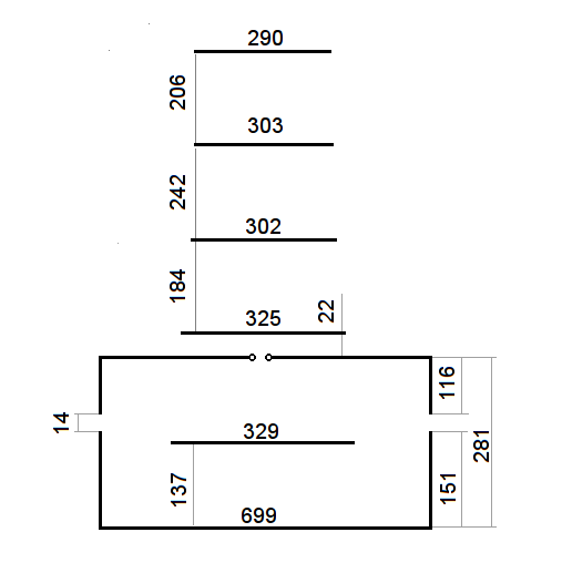
I had a listen on my colinear antenna and I could hear some stuff on the downlink frequencies, but the received signal was poor. I needed a decent antenna. I was recommended a design on SA555 blogspot by LY3LP. An image of which is extracted below:
The issue is that once I built the antenna to this design, the SWR was over 2:1, which I didn’t think was good enough. Dad and I messed around with the design, and managed to get the SWR lower, but we decided to simulate it and get the measurements correct. Presented on the rest of this page is our refinement.
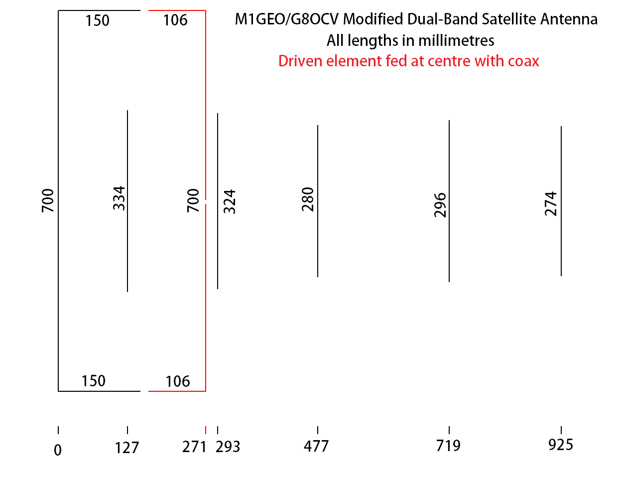
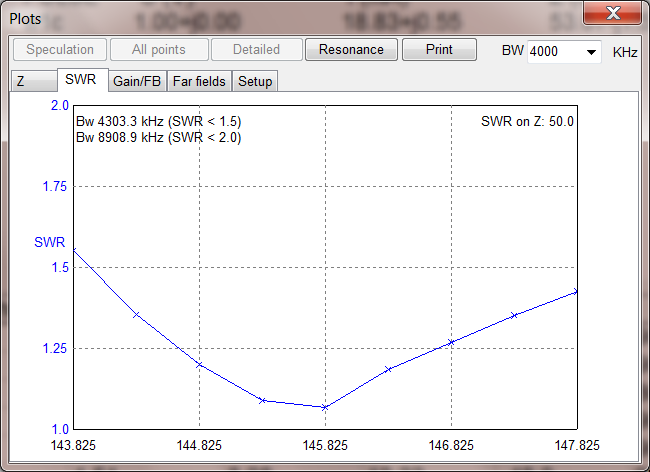
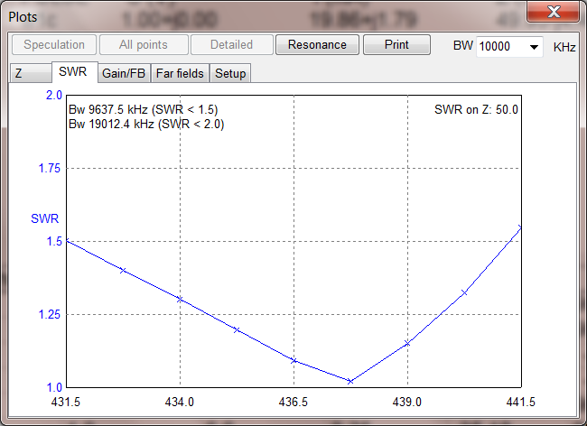
The antenna is a VHF side is a 2m Moxon rectangle, tuned on 145.825 MHz. The driven element of the Moxon passively couples to a driven element for a 5-element 70cms Yagi, tuned on 436.5 MHz. A good SWR below 1.2:1 (see simulations below) is obtained on both 2m and 70cm in the satellite sub-bands.
The dimensions are all in millimetres, with element length next to each element, and spacing along the bottom. The red element is the driven element, and is broken into two pieces and fed with coax. Wrapping several turns of feeder around the boom will serve as a choke balun at these frequencies, and should be sufficient.
The antenna is made from 3.2 mm aluminium welding wire, using 10 gauge saddle clamps (used for model aircraft) fixed to a wooden boom such as 15mm square boom or inch diameter dowel. All the parts come from eBay.
Ondra OK1CDJ prepared 3D printable element supports for this antenna, which can be found on the Printables site.
Simulation Files
The antenna was simulated in MMANA-GAL Basic V3.0.0.31, which can be downloaded from http://gal-ana.de/basicmm/en/ and is free for non-commercial uses such as ours.
The simulation file (in MMANA-GAL’s native MAA format) can be downloaded here: M1GEO-G8OCV_Dual_Band_Satellite_Yagi.zip
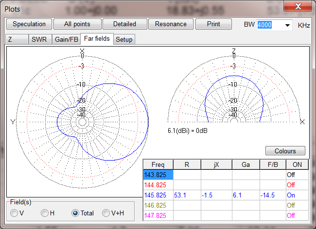
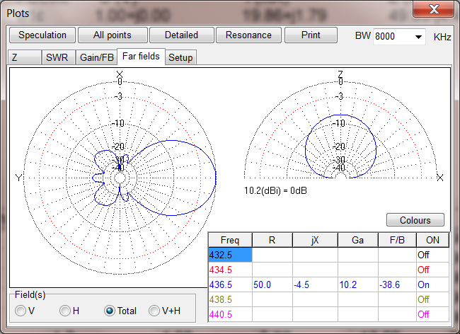
The first table below shows the free-space parameters for the antenna:
| Frequency (MHz) | 145.825 | 436.500 |
| SWR | 1.07:1 | 1.09:1 |
| Forward Gain (dBd) | 3.95 | 8.06 |
| Front to Back (dB) | 14.53 | 38.58 |
This second table shows the real ground predictions when hand held around 1.5 metres above the ground (Dielectric constant 13.0, conductivity 5.0 mS/m):
| Frequency (MHz) | 145.825 | 436.500 |
| SWR | 1.13:1 | 1.09:1 |
| Forward Gain (dBd) | 9.03 | 13.50 |
| Front to Back (dB) | 15.34 | 16.99 |
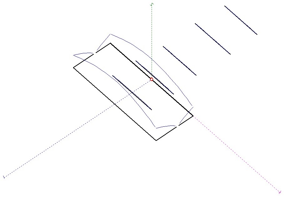
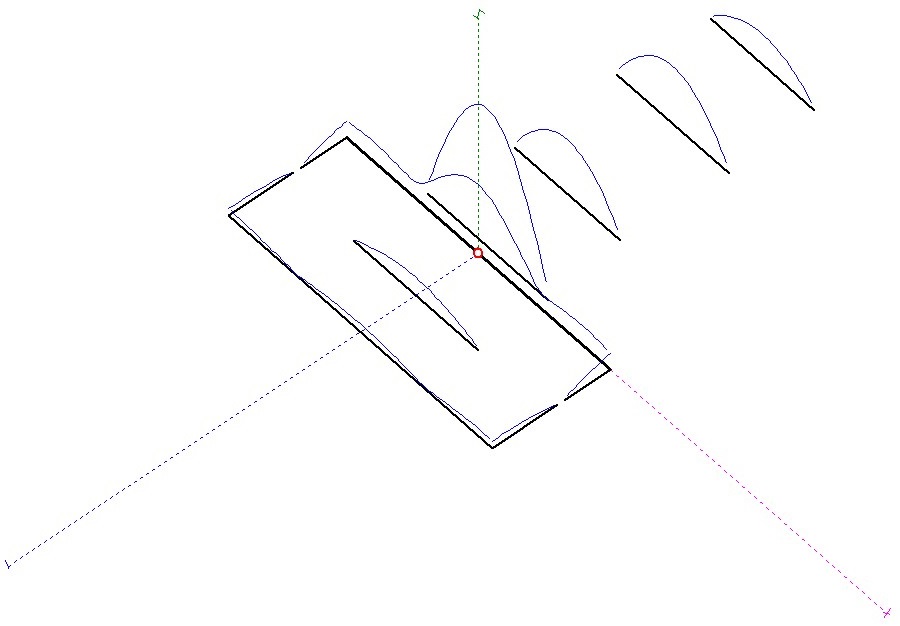
The below images show the SWR, plots and currents for the modified antenna design:
Clicking on any of the pictures will load the picture details page. Click on the picture there, and it will show full resolution.
Below, the two plots of the antenna on 2m and 70cm when used 1.5m above a real ground.

