EIRP Calculator
I started writing an ERP calculator for low and medium frequency, though it would cover any electrically short antenna. The calculator can be found here: LF/MF ERP Calculator. More information and notes on the theory can be found here on the Electrically Small Antenna ERP page.
Antenna
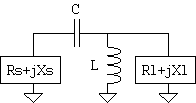
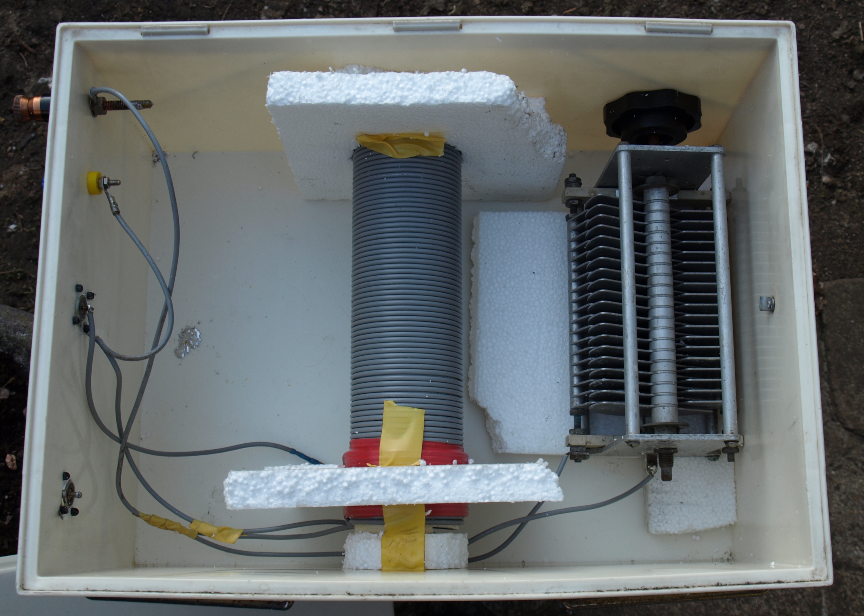
I firstly measured the impedance of the unmatched inverted-L wire and found it to be ![]() . Using these values, it is possible to calculate a matching circuit – you may find a calculator, such as this website helpful. Using the linked website, I settled on a high-pass (because the components worked out nicer) low-to-high matching LC-network. From the matching circuit on the right, I found the values L=133uH and C=437pF worked ideally. We tried with some low power components to check that the values were correct, before winding a big inductor from plastic insulated wire around a 4 inch drainpipe. Mini Ring Core Calculator was used to calculate the number of turns of the given wire for a given pipe diameter. Once that was tested, we lashed up a frame to hold the capacitor and inductor from the ground and inside a box to give a slight amount of cover. The box has a waterproof seal.
. Using these values, it is possible to calculate a matching circuit – you may find a calculator, such as this website helpful. Using the linked website, I settled on a high-pass (because the components worked out nicer) low-to-high matching LC-network. From the matching circuit on the right, I found the values L=133uH and C=437pF worked ideally. We tried with some low power components to check that the values were correct, before winding a big inductor from plastic insulated wire around a 4 inch drainpipe. Mini Ring Core Calculator was used to calculate the number of turns of the given wire for a given pipe diameter. Once that was tested, we lashed up a frame to hold the capacitor and inductor from the ground and inside a box to give a slight amount of cover. The box has a waterproof seal.
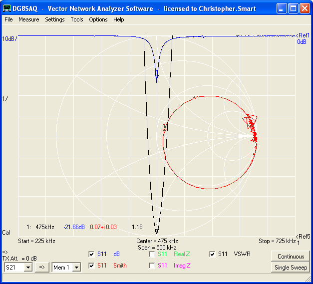
Once the matching network was built, the antenna was remeasured. From the plot we can see the VSWR is 1.18:1, with a matched feed impedance of ![]() on 475 kHz. As you can see, the real part of the antenna impedance is close to
on 475 kHz. As you can see, the real part of the antenna impedance is close to ![]() while the complex (reactance) part is almost
while the complex (reactance) part is almost ![]() , which indicates a good match. This is, of course, confirmed with the low SWR. I decided this was close enough to start off with!
, which indicates a good match. This is, of course, confirmed with the low SWR. I decided this was close enough to start off with!
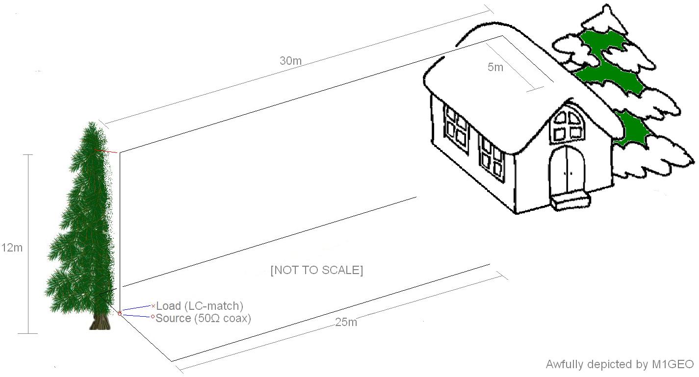
Below is an awful depiction of the antenna set up. I shall try to make a better one soon; sorry.
The lower two pictures are a view up the tree where the inverted L runs. At the top the inverted L meets the end of the G5RV, both of which run back to opposite corners of the house.
 |
 |
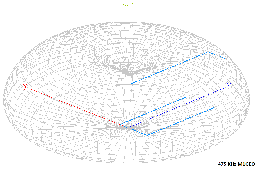
Finally, the radiation pattern as forecast by MMANA-Gal:

