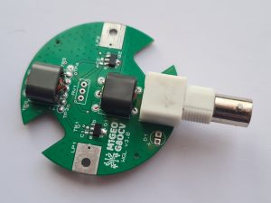
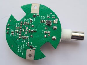
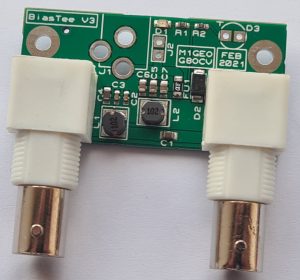
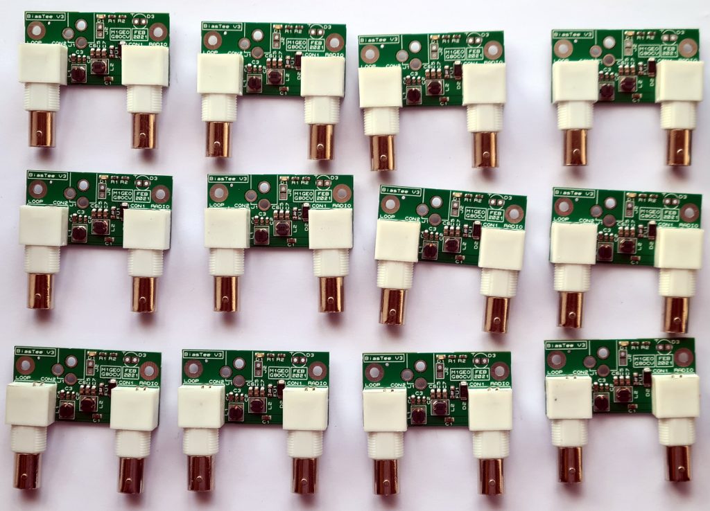
This page documents the version 3 and version 4 WellGood Loop project which was originally devised to help repair the WellBrook Loop ALA1530. The history and earlier versions of the project, including schematics and details of operation can be found on the WellGood Loop History page. You are advised to skim through that page if you are new to the project.
Be aware that there are several poor copies of older Wellgood Loop designs on the internet, both from Russian and Chinese sellers. See the bottom of this page for more information.
If you are interested in this updated version of the WellGood Loop Project, please email Chris G8OCV, stating clearly what you require and where you are located. Please be aware that it can sometimes take a bit of time to get back to you! 🙂
You can listen to a WellGood Loop V4 in action on my M1GEO KiwiSDR in Norfolk or at GB0SNB KiwiSDR in Essex. Both receivers are running V4 boards due to their superior performance and increased reliability.
The version 3 and version 4 boards are closely based on earlier versions of the WellGood Loop project, but address some of the more common asks of the project:
- SMT passives allows for factory assembled boards.
- SMT transistors dissipate heat into the PCB substrate, providing heatsinking & thermal coupling between transistors.
- New high frequency transistors allow for higher frequency operation and better overall signal to noise ratio.
- Design improvements enhance gain at higher frequencies, and eliminate the need to perform initial setup.
- PCB fits inside electrical trunking box, allowing for easy mounting in waterproof box.
- Increased voltage operating range (for battery/portable use).
- Various other small schematic tweaks.
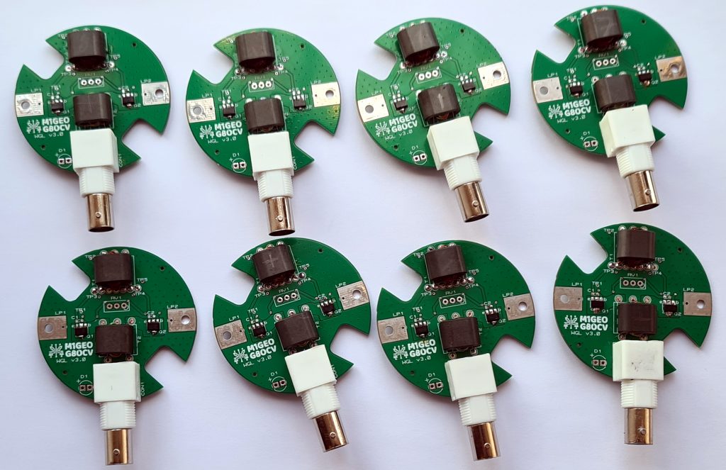
Based on interest in the earlier versions of the repair, along with interest in the improved version on Twitter, I have had a small production run of the new loop amplifier and bias tee boards made.
All boards are tested and just need a loop and box, and a DC power connection of your choice.
The loop, approximately 1 metre in diameter, connects between LP1 and LP2 connections. A BNC cable connects between the amplifier PCB and the bias tee, with 12V DC (approx 130mA draw) supplied to the bias tee.
The loop amplifier PCB has cutouts for electrical trunking style boxes, such as 3 way 20mm PVC Conduit Box, although you can of course use any box. You are advised not to attempt to make the box completely air-tight, since with daily temperature cycling enclosures always suck air in as they cool, bringing in moisture. A better approach is to have a small drain hole on the bottom side of the loop to allow the pressure inside the box to equalise easily with outside, as well as any moisture to drain away.
There is provision on the loop amplifier board for external LED, part D1, (not provided) is useful for showing the board is powered. SMT LED part D3 shows power on the board itself but may be difficult to see once enclosed.
If marked on the PCB, parts RV1, C1 and C2 do not need to be fitted.
The history and earlier versions of the project, including schematics and discussion of operation can be found on the older WellGood Loop History page. You are advised to skim through that page if you are new to the project.
3D Printed Cases
James M1DST has designed a 3D printable case for the bias-tee which can be found here: Printables.com: WellGood Loop Bias Tee Enclosure.
eBay Listings
If you’ve followed a link here from an eBay listing, these are (likely Russian) clone boards are based on the older V1 design. The project history page may help you – any enquires about clone boards should be sent to the seller.
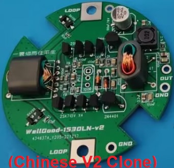
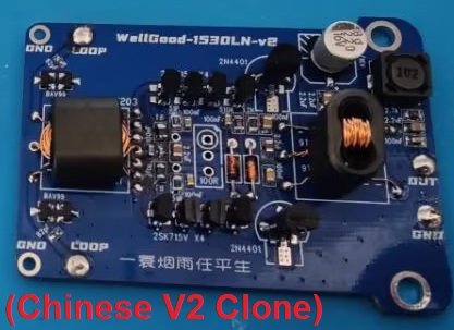
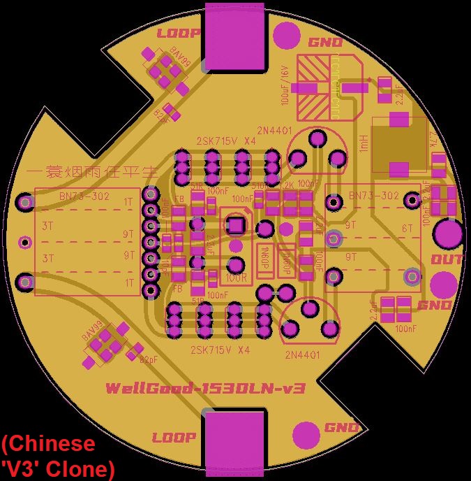
If you have arrived here from a Chinese board (possibly titled “V2” or “WellGood-1530LN-v3”, like below), then these boards are a strange take (why so many transistors?!) on the V1 design and the project history page may help you – any enquires about clone boards should be sent to the seller.

