Category Archives: Construction

Comparing Preamps

A couple of evenings this past week, I have stayed late at work to compare masthead pre-amplifiers. I have been able to measure their gain using the Rigol DSA-815TG we have at home. But only recently have I been able to measure the preamp noise figure.

During the RSGB Convention 2017, I was chatting to some of the big names in ham radio, especially in terms of VHF and upwards. Part of my quest to get better at EME, if I recall. Ian (GM3SEK), designer of the DG8 preamp, pointed out that the DG8 was unsuitable for EME reception and suggested a PGA144 preamp as designed by Sam (G4DDK).

I had built a few other preamps, too, and I decided to measure their gains and noise figures to see how things compared.

The first few I tested were:

  • DG8
  • PGA144
  • OK1ZI
  • DEM L144LNA

GM3SEK DG8

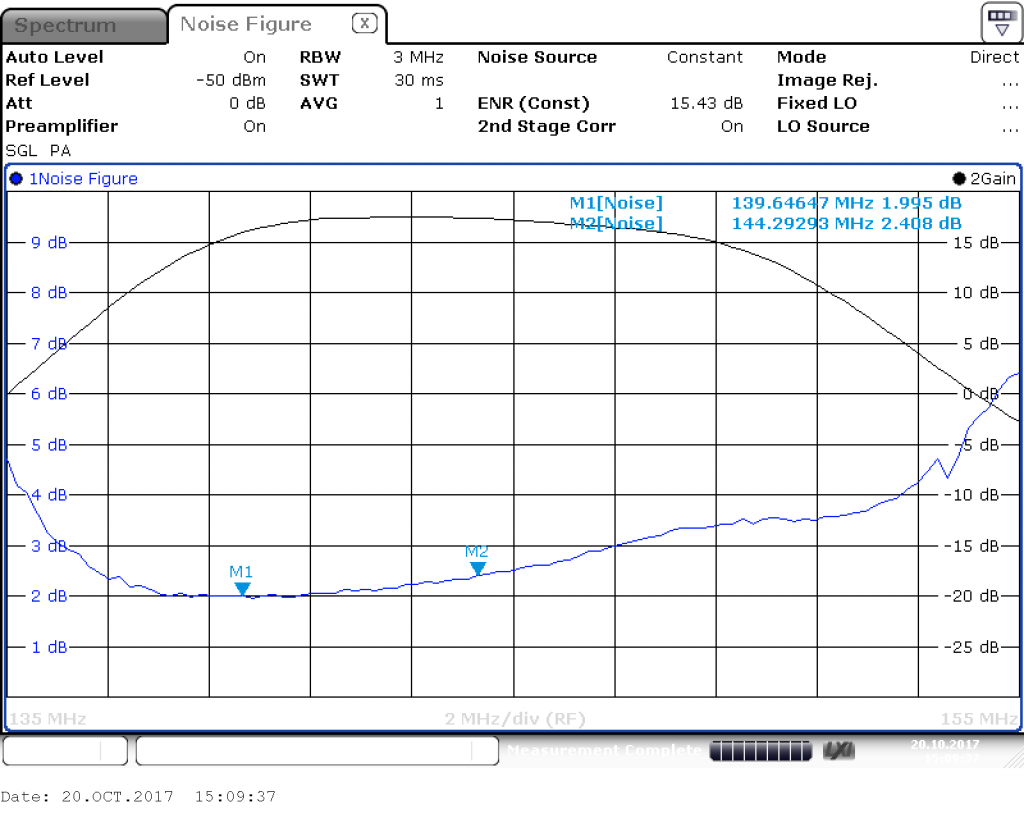
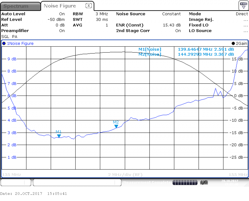
I measured the two DG8 preamps, and found the maximum gains to be around 18dB. The noise figures on 144 MHz were 3.4dB and 2.4dB. The 3.4dB device was retuned to obtain a better noise figure at the cost of a (slightly) lower maximum gain.
G4DDK PGA144

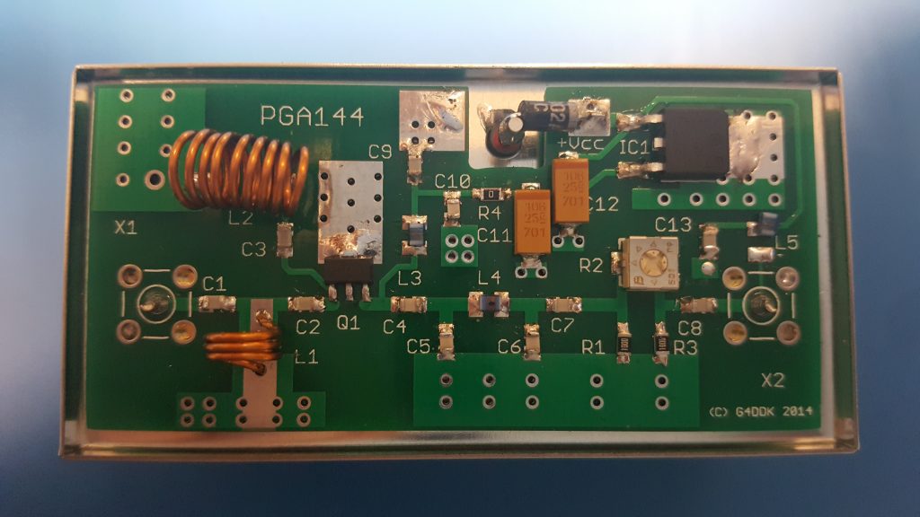
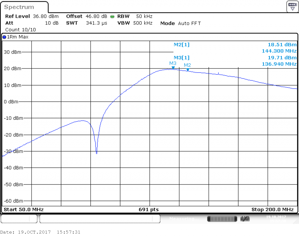
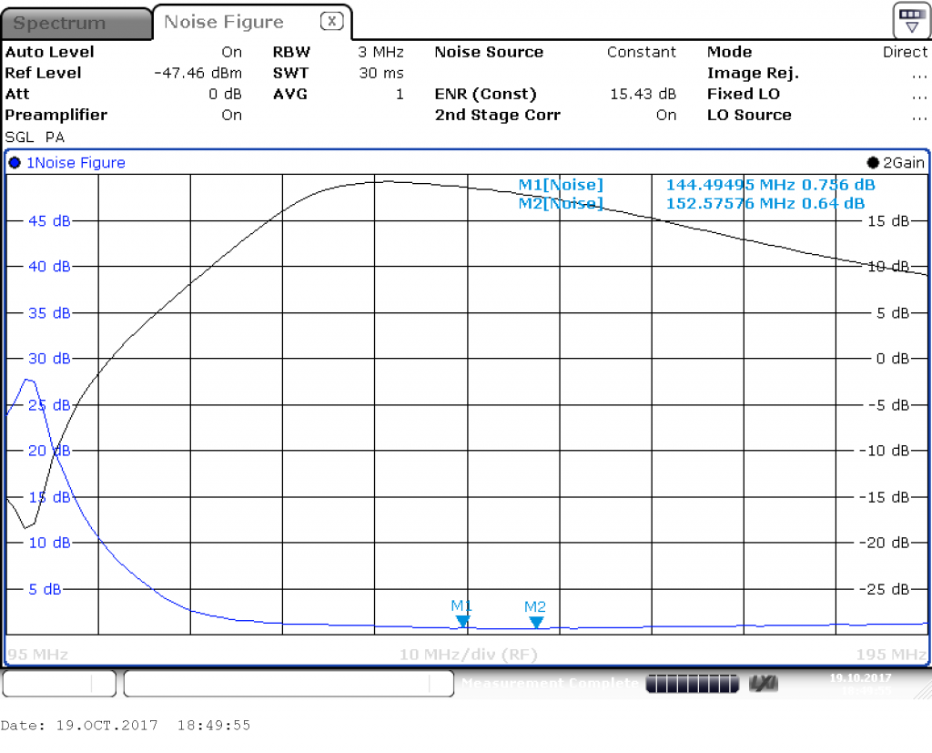
It is easy to see why the PGA144 preamp is better for EME. The PGA144 is based on the PGA-103+ device by MiniCircuits, with a FM band notch and a high pass filter. Compared with the DG8, the PGA144 has a similar gain, but a much lower noise figure, at 0.64dB minimum and 0.74dB at 144.5 MHz. The top graph shows the tuning of the 98 MHz notch filter (for FM broadcast). The second graph shows the gain and noise figure.
OK2ZI PGA-103+

The OK2ZI design was brought as a PCB on eBay. It’s based around the PGA-103+, as is the PGA144. However, the OK2ZI design is unfiltered.

In order to get a large range of frequencies in one sweep, the output was displayed on spot frequencies as a table, instead of as a graph in previous cases. The frequency range includes all of the amateur allocations. The device supports 50 to 4000 MHz.

Frequency (MHz) Noise Figure (dB) Gain (dB)
51.0 0.411 25.8
70.2 0.285 25.7
145.0 0.217 24.7
435.0 0.249 20.8
1296.0 0.824 11.6
2304.0 2.459 3.5

Down East Microwave DEM L144LNA

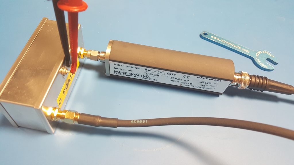
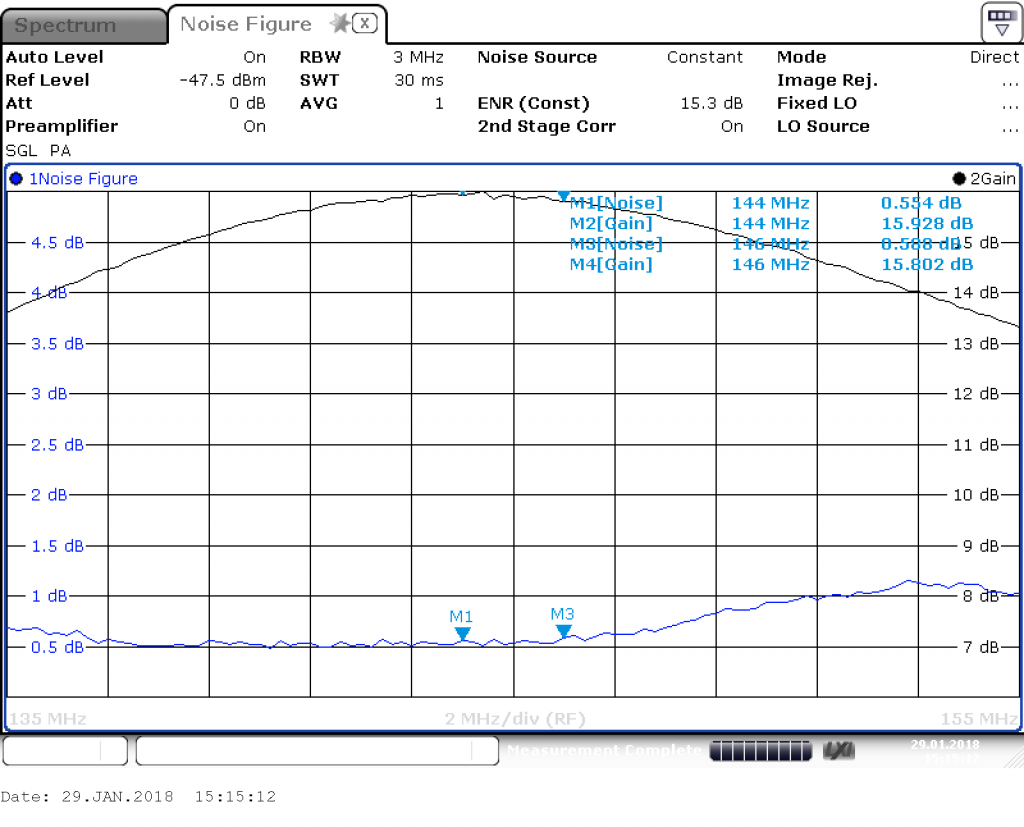
The DEM L144LNA I had floating around in my shack for a while. I had built it up but not used it. It was originally purchased as a low-noise device, but is slightly older than some of the other designs here. On the 2m band, the noise figure was found to be 0.55 dB NF and the maximum gain around 16 dB.

1kW 144MHz Amp Lives!

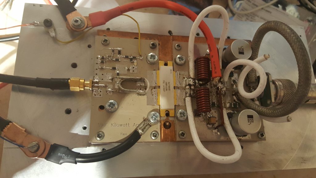
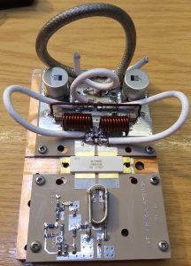
Those of you who have been following my 144 MHz 1kW amplifier project (previous posts machining heatsinks, soldering transistor down and building the pallet) will, I’m sure, be delighted to hear that I have had life out of the amplifier. In excess of 1 kW, I hasten to add!

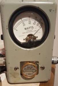
The amplifier was able to maintain in excess of 1000W for over 2 minutes.  At this point, the Bird dummy-load started to get a bit warm, so a longer test was abandoned. The amplifier pallet, however, remained cool enough to touch. As the F1JRD original design notes, the 10-Ohm coax balun does become hot (Lionel suggests around 120C at 1kW with no cooling). I, however, used a small fan running slowly to provide a gentle draft which greatly reduced the balun heat.

The next step is to add the Dallas-Maxim DS18B20 temperature sensor – the idea is to have the sensor buried into the pallet next to the transistor, to measure the copper heat spreader temperature.

BA5SBA RTL-SDR Kit

A few weeks ago I ordered a BA5SBA RTL-SDR direct sampling kit from BangGood (link here). When it arrived, I decided to put it together. The kit includes everything needed, an RTL-SDR dongle, case, PCB, enamelled wire and so on. I worked from numerous build instructions (here, here, here and here), following the clearest description of each stage.

I disassembled the original RTL-SDR dongle, removing the USB plug, IR remote receiver and Belling-Lee socket. This was easy to do. I then soldered the module into the main PCB. The SMT components were easy to solder on. I added the few remaining passives, some larger electrolytic capacitors, etc.

Two wires tack on to various voltage points to add extra smoothing, which were easy enough to connect – I used some medium thickness tinned copper wire, I guess around 0.7mm diameter. That did the trick.

Winding the two inductors was done blindly. I followed instructions to wind 8 turns around a 5mm drill; however, somewhere else said 6-9 turns around 3mm. I noticed after soldering in the coils that 300nH was the suggested inductance. In the future I will remake the coils to the correct value.

Winding the small transformer, T1, was relatively straight forward. I wound 8 turns around the ferrite core. Although I’m not entirely sure my core was ferrite. It was indistinguishable from a 2mm plastic washer. My kit had blue-red-yellow trifiliar wire in, so I followed the colour scheme in the 3rd instruction link above (page 11).

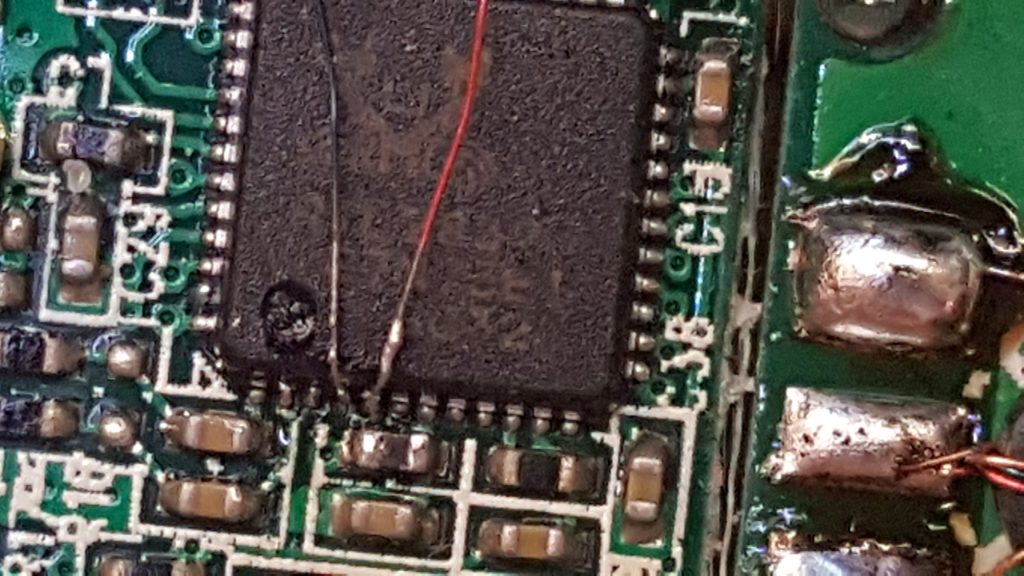
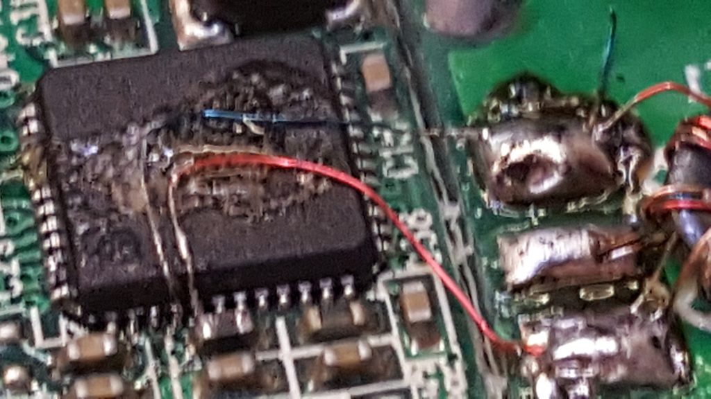
The chip has two pairs of I-Q inputs, pins 1, 2, 4 and 5. The first pair, pins 1 and 2 are connected to the E4000 front end, which mixes the higher frequency signals of VHF and UHF down to an intermediate frequency (IF). The second pair are also used in this kit to take the HF bands (on the Realtek RTL2832U, 0-24 MHz) as a second IF input. A “direct sampling” mode can be selected in the PC software to select this second input, but, there is no default wiring as this has no use inside a TV tuner dongle. By far the hardest part of this build was the soldering of hair-sized wires to the Realtek RTL2832U chip, which then go to the transformer, T1.

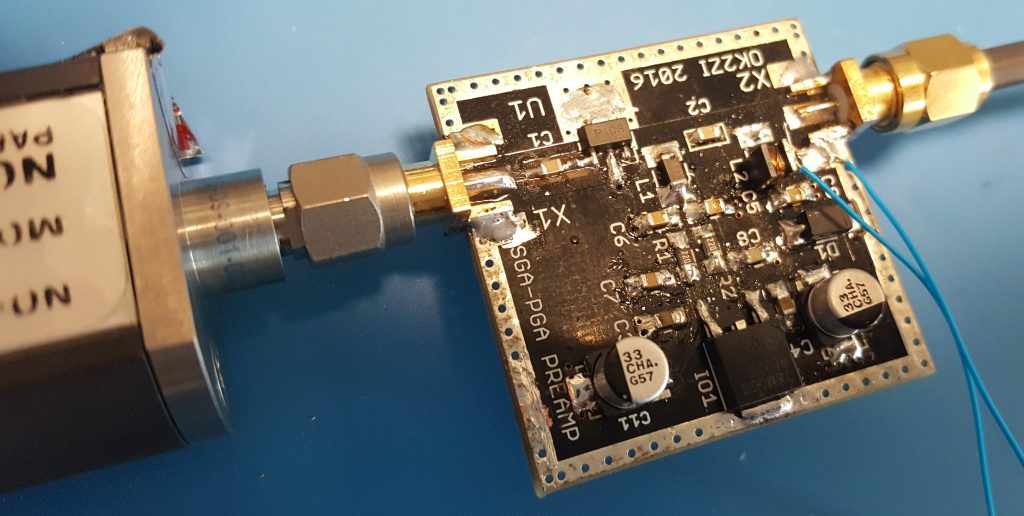
After a considerable struggle, these two wires were solder onto the chip. I wish I could offer some useful tips on how I did this, but I cannot – I simply struggled, and faffed around until I made the connections. I would suggest a mobile phone camera placed above the board may help, since you can use the digital zoom to see in some detail. The image above was taken as I was soldering.

Finally, I used some glue to hold the (very) fragile wires in position and soldered the other ends to the transformer. I also added a small amount of glue to the transformer, too, so as to stop it moving. It looks messy, I know, but hopefully it will add some security and stability to those otherwise poor solder connections to the Realtek chip.

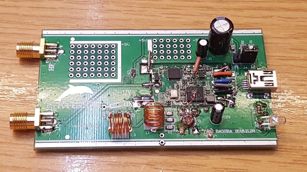
My final build looked like this:

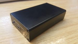
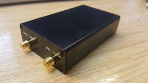
Amazingly it also works! The image at the top shows the device inside the supplied box! Excellent!

1kW 144MHz Amp Pallet

Those of you who have been following this project evolve will have seen how I soldered the transistor to the heat-spreader and before that how I machined the heat-spreader & heat-sink after their initial use. Most recently, I have been building the new W6PQL pallet, based on the revision 4d schematic, found here.

This pallet offered several design changes compared to the original F1JRD design. The first is temperature tracked biasing for the FET. The F1JRD pallet didn’t have temperature tracking, but the W6PQL design uses a combination of 10kOhm and 22 kOhm NTC thermistors to track the temperature change of the pallet. A 6V Zener diode is used to clamp the bias supply and to also limit the maximum gate voltage the FET can see. A small 200 Ohm pot allows the bias to be adjusted to get the correct quiescent current. This is the next task.

The story continues with the initial power-up testing! First I need to commission my new General-Electric 50V/40A PSU I brought at the Rosmalen Hamfest back in early March.

BNOS LPM144-10-100 Repair

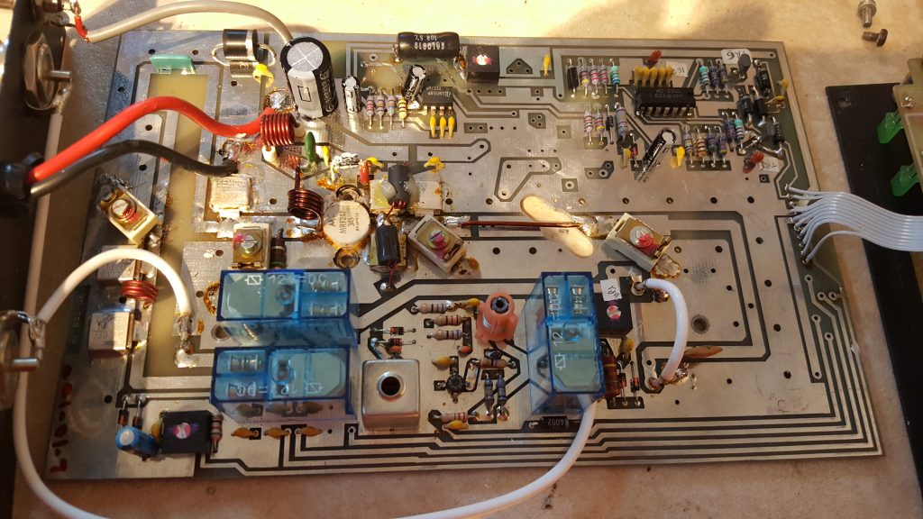
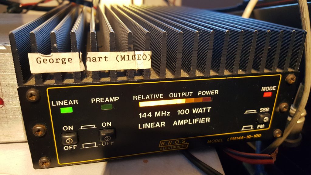
I have had a B.N.O.S LPM144-10-100 solid state linear amplifier for some time. It brought it at a ham fest and it worked fine. However, when I tried to use it recently, I noticed that sometimes the amplifier would work, but other times there was no output. Due to the intermittent nature of the fault, I knew it couldn’t be the main power transistor (MRF247). The most likely cause was one of the 3 relays. There were also 5 electrolytic capacitors. I decided to change all 8 parts.

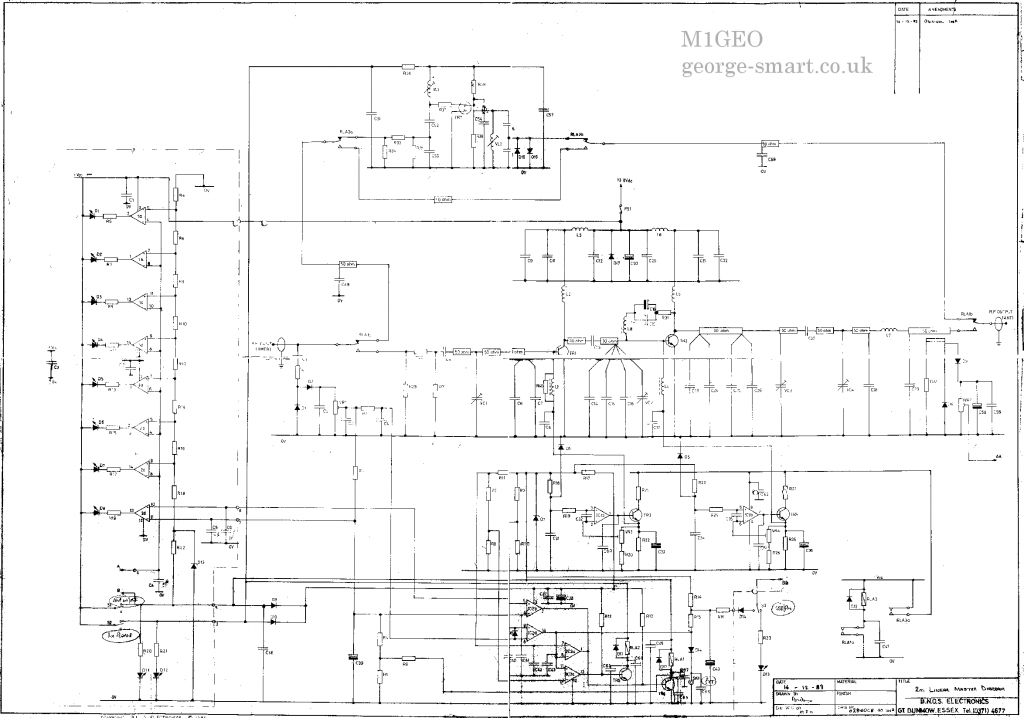
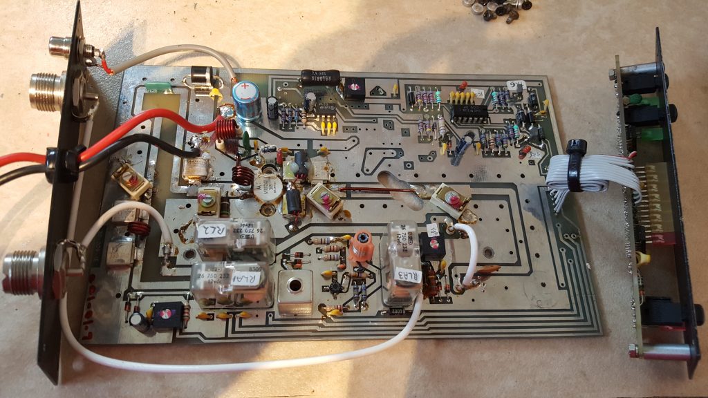
The first thing I did was cross correlate what I had with the circuit diagram (click for full size image/download).

The PCB 

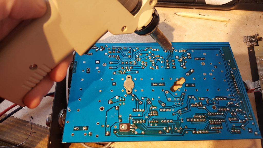
Using a desoldering station to melt and vacuum extract the solder, the 3 relays are easily removed from the PCB with no board damage.

Closeup of the 3 removed relays:

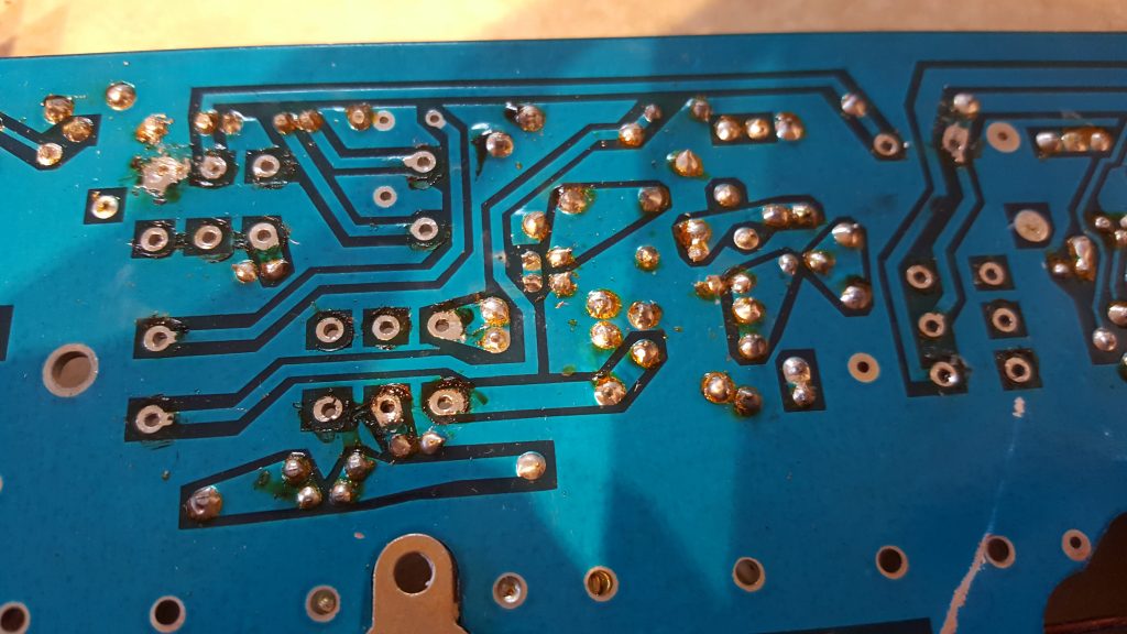
Comparing the original PCB photo with the one below, you can see the 3 replacement relays and 5 capacitors.

I used a Finder 12V miniature DPDT 8A relay as my replacements sourced from Rapid Electronics in the UK, but these relays are universally available from different manufacturers. You will need a DPDT relay with 12V coil (not SPDT as this article previously stated [thanks to Keith GM4YXI for spotting this issue]). My current suggestion would be the TE Connectivity / Schrack RT424012 (datasheet).

Below is the amplifier working! Yay!

Soldering Expensive Transistors

This morning, Royal Mail delivered me a parcel from Jim W6PQL all the way from California, USA. It took a couple of days to clear customs, but it arrived within about 5 days of being ordered. If you followed my previous post on this subject, about machining heatsinks, you’ll know that the last transistor I had failed on the testbench. You’ll also know that the copper heat-spreader was re-machined to suit the new PCB. This is why the heat-spreader has a few extra holes. Seeking advice from veteran microwave DXers & constructor (G4BAO, G4DDK, G8KBV, et al.) I was instructed to solder the device down. I watched a few of Jim W6PQL’s videos on soldering LDMOS parts to the copper heat-spreaders and replicated his instruction as closely as possible. You can see Jim’s instruction video here.

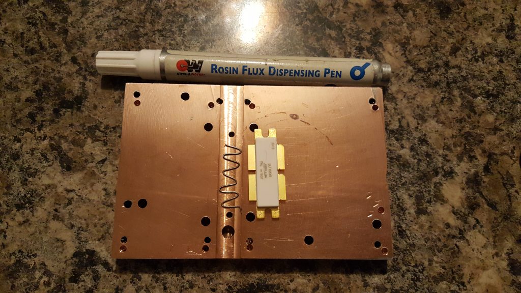
A small length of thin leaded 60/40 solder was made into a wiggle for the length of the transistor and placed in the groove previously machined in the head-spreader. I liberally applied flux to the bottom of the groove and the underside of the transistor and then sandwiched  the solder in between.

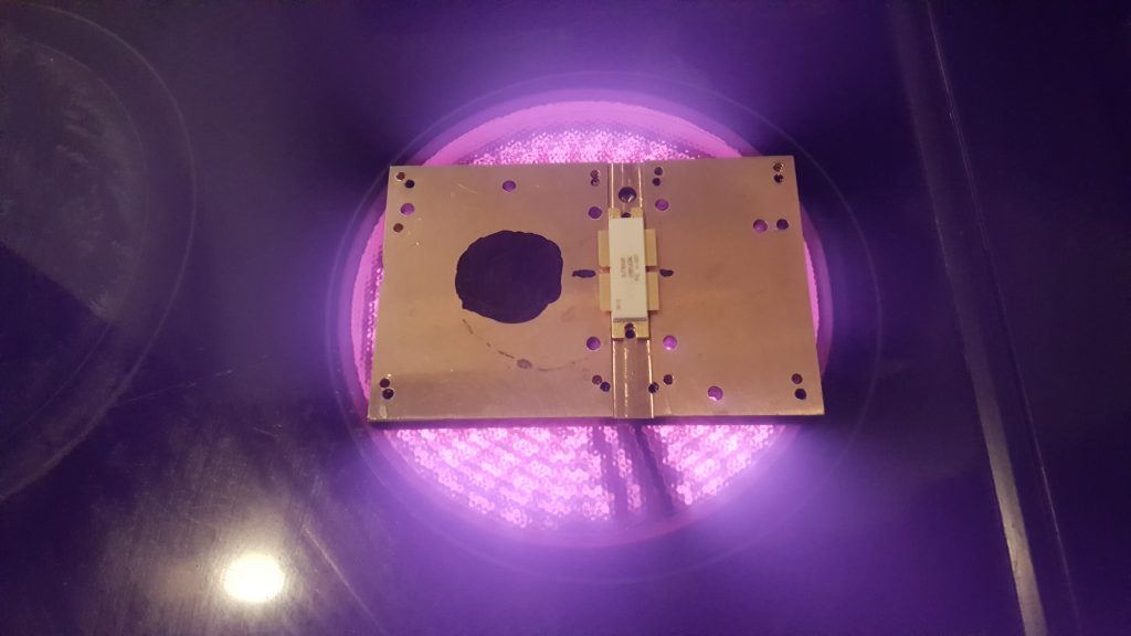
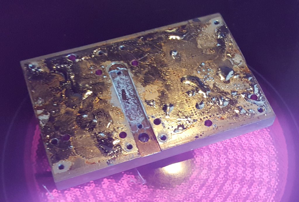
The copper heat-spreader was placed on the electric infrared hotplate and heat applied. The black dot is used to allow a laser thermometer to monitor the copper temperature. NB: this method didn’t work well.

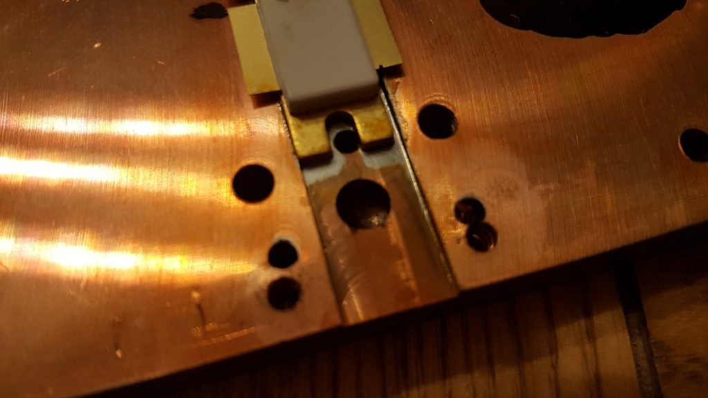
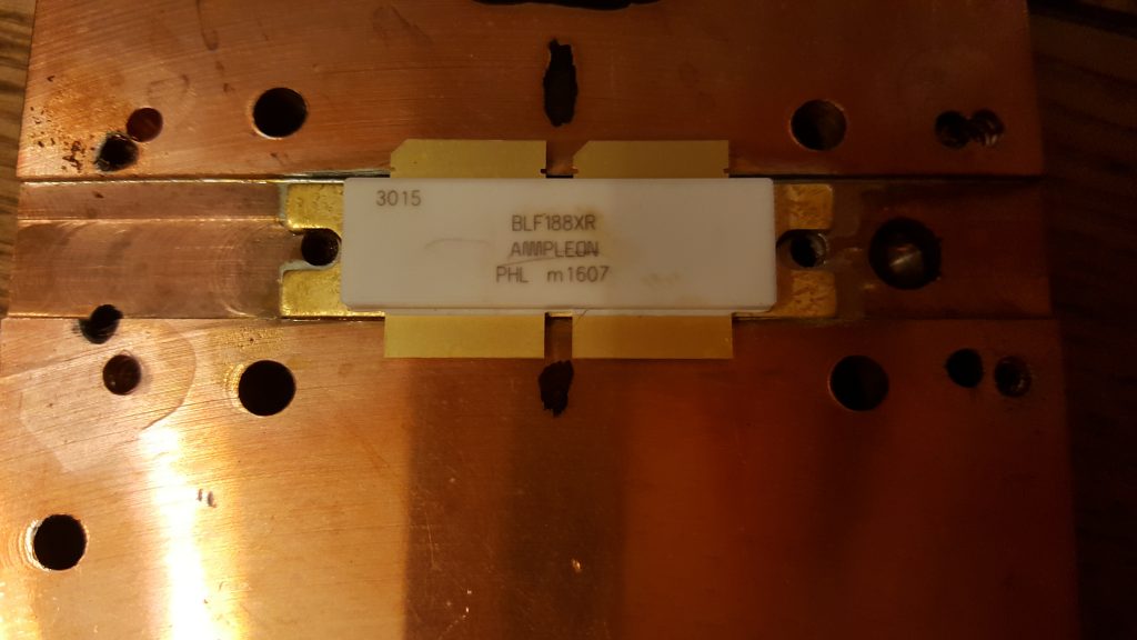
The next two images show the solder has melted and the excess squidged out the sides. It’s clear to see when the solder has melted, since the the transistor drops. It is advised to move/slide the transistor in the molten solder to remove any voids and any excess solder. I immediately killed the heat and removed the spreader from the hotplate and placed it on a heatsink. It only took a couple of minutes to cool to a temperature I could handle, and I checked the location of the transistor against the PCB mounting holes.

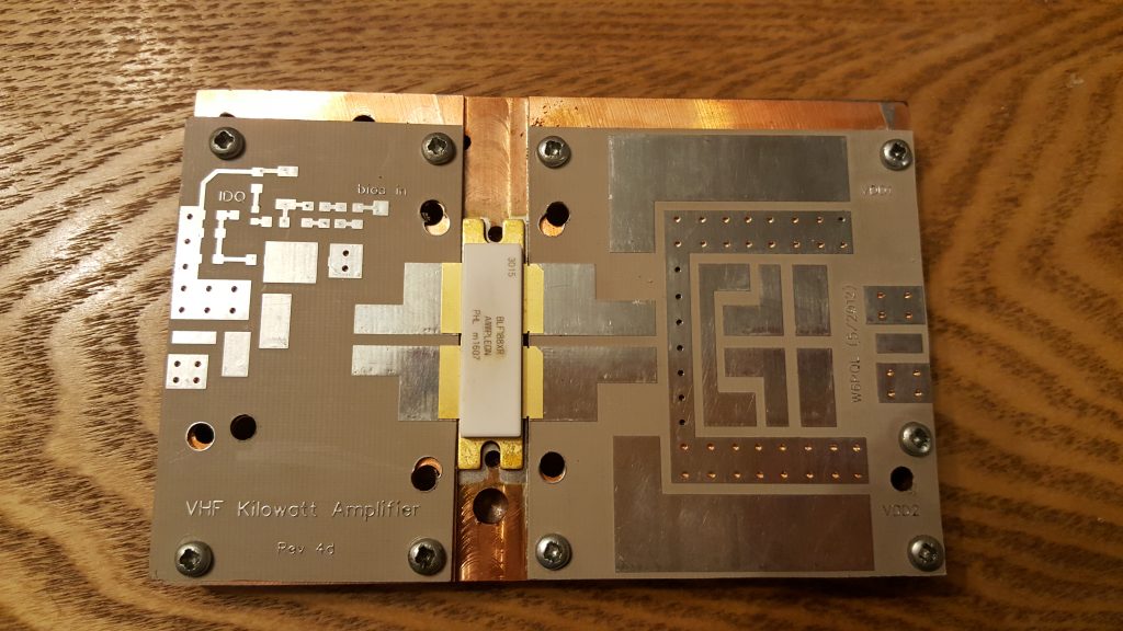
The PCBs were finally mounted as a test fit. I will populate the boards before mounting them. Unlike the original jrd1 boards, these PCBs do not need to be soldered down. This means the boards can be soldered up and then mounted.

Stay tuned for more updates…

Earth Fault on Yaesu G-5400B

I brought a Yaesu G-5400B azimuth and elevation rotator & controller system from a friend at a local radio club about 6 months ago. I brought the rotator as faulty. When I powered the rotator up on the bench, I couldn’t find any fault. I built a PC-Rotator controller interface similar to the Yaesu GS-232 interface to accompany the G-5400B controller, and while doing extensive testing, no fault with the rotator became apparent.

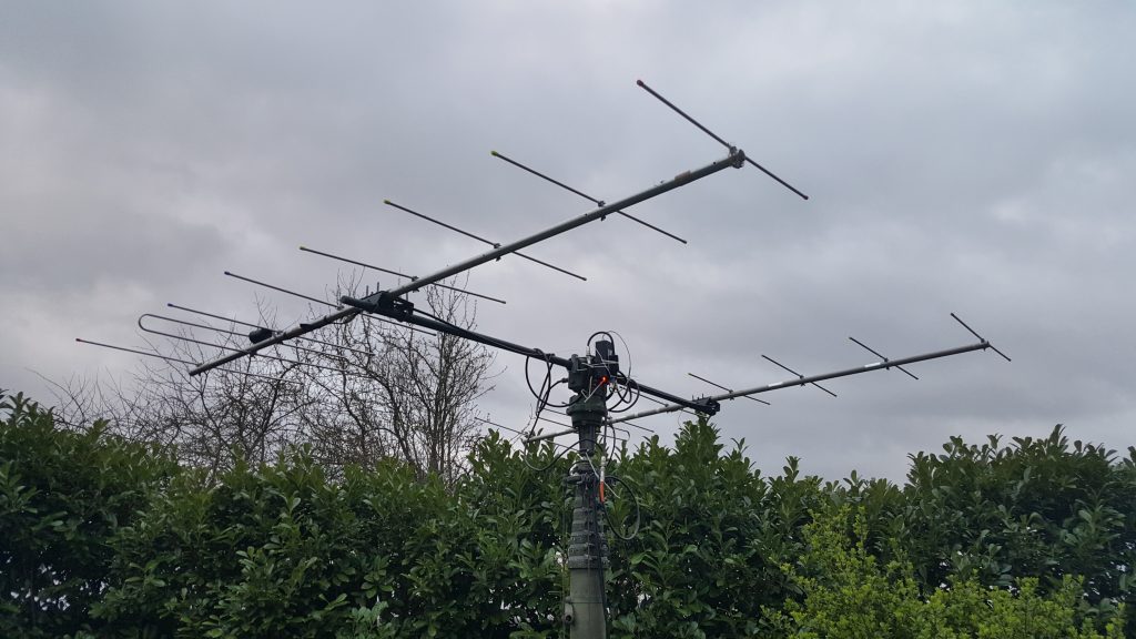
This weekend, following the acquisition of some fibreglass poles at the Rosmalen hamfest, I decided to set up my bayed 144 MHz beams with the azimuth/elevation rotator. After mounting the antennas on the beam, fixing the phasing harness and the mast-head preamp and connecting the cabling, I noticed that the rotator was no-longer working correctly. Although both of the rotators would turn, the azimuth display on the control box failed as soon as the coax was connected to the radio (or more specifically, the coax screen connected to anything in the shack that was earthed).

Using a multimeter to inspect what was going on, it was clear that the coax ground was sinking current sent to the potentiometer inside the azimuth rotator. Looking at the schematic, the cause would appear to be that the +6V side of the feedback potentiometer was somehow becoming shorted by the connection of the coax screen.

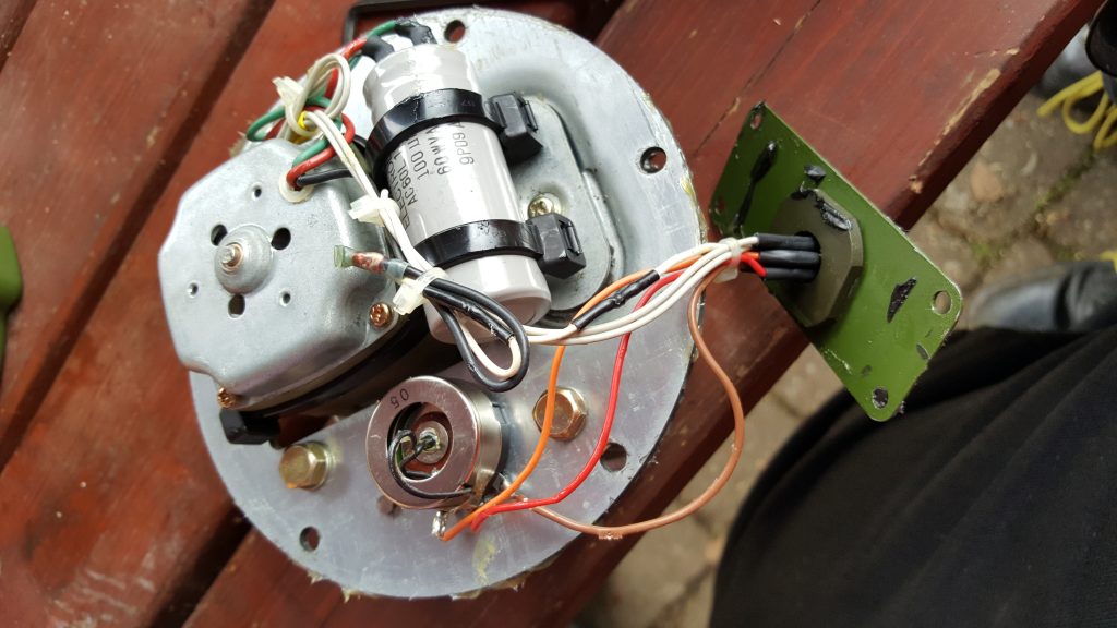
I decided to pop the cover and see what was going on

From inspection, you can see that the original hypothesis was correct and that one side of the potentiometer was shorting to the casting – the brown wire had been caught between the plate visible and mounting point. Since the antenna metal is grounded via the coax, this effectively shorted out via the broken insulation on the brown wire.

The repair was the simple process of snipping the broken wire, and soldering a new one in. I also used two tiny cable ties to bundle the wires to the potentiometer and to ensure they were kept away from the mounting hole, too.

The rotator goes back together easily assuming you have followed the usual advice when dismantling these rotators; marking the case and internal gear such that it can be reassembled with the same aligning.

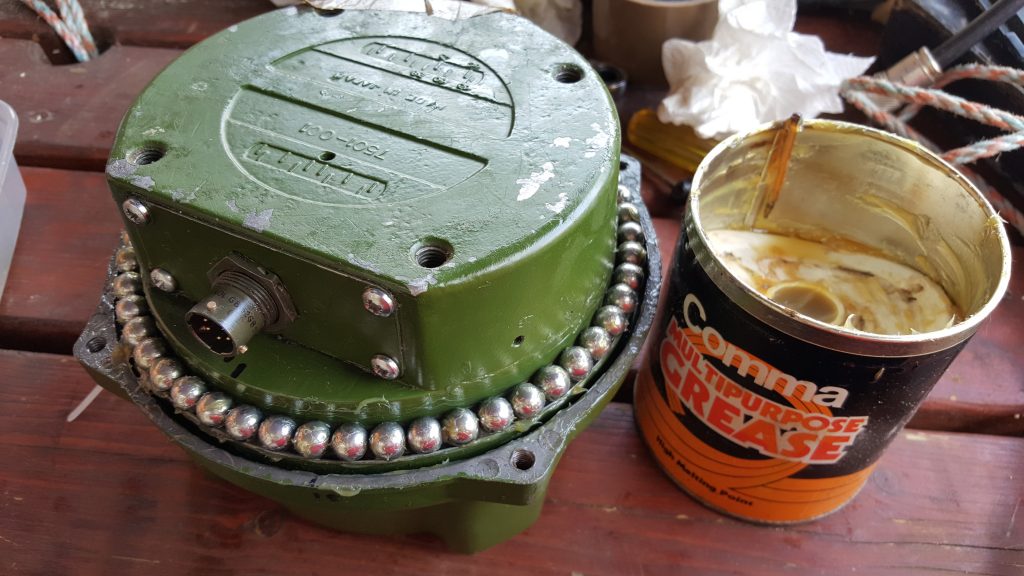
After finishing the reassembly of the the G-5400 rotator, being sure to grease the bearings, I was ready to mount the antennas and try again.

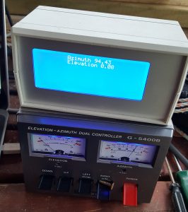
This time around, the rotator functioned perfectly. The total repair took around an hour. Now I need to finish the PC interface to make use of the fancy graphics LCD!

Machining Heatsinks for QRO Amplifiers

Back at the 2012 Friedrichshafen Hamfest I brought a 1.25 kiloWatt VHF amplifier kit for 144 MHz from F1JRD and F5CYS. These devices were fairly new at the time. It took me a year to pluck up the courage to build the pallet, but I went about it all wrong. With the help of Dad and the kitchen hob, we soldered the jrd1 Teflon PCB to the C110 copper heat-spreader as suggested in the Dubus article (see here). I had the pallet working at the time, giving around 600W of RF, which was about the maximum my 1000W 50V PSU was capable of sustaining. When I came to boxing the device up into an amplifier to use with EME and Meteor Scatter in late 2016, the part failed under test.

After much deliberation, I have ordered parts to repair the amplifier project. I found Jim W6PQL‘s website (see here) a wealth of information, and Jim also offers to supply parts and designs to help others. I ordered a set of PCBs to replace the original jrd1 board, a NXP/Ampleon BLF188XR 1400W part to replace the failed the Freescale/NXP MRFE6VP61K25H 1250W part, and some other accessories that Jim sells. The parts were posted by Jim today, so I decided it was time to recover parts from the old PCB and recondition the heatsink and heat-spreader.

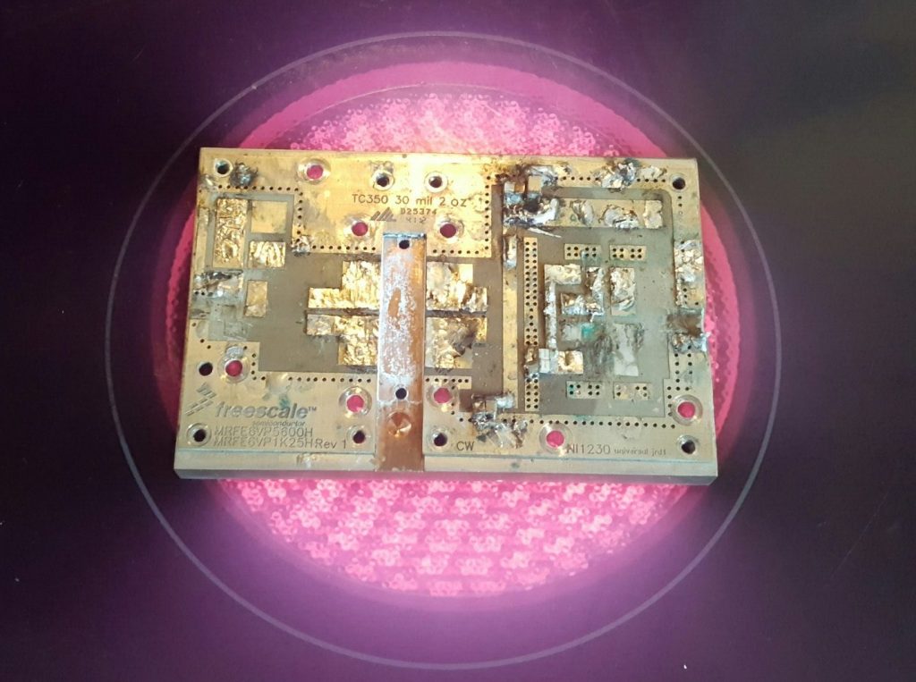
The first step was to remove the jrd1 board from the copper heat-spreader. I used the kitchen hob to heat the copper heat-spreader, since the old board was soldered to the copper block. The board damage was sustained to enable the removal of the more expensive components.

Below, the heat-spreader with the jrd1 board removed. I used a solder sucker and scraper to remove as much of the molten solder.

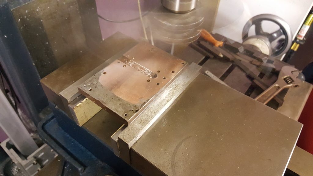
Once the heat-spreader had cooled down, I mounted the copper spreader up in the milling machine read to re-machine the top and bottom surfaces. Great care was taken to level the block using parallels. Below you can see the fly-cutting process on the first cut, removing just 0.05mm from the surface.

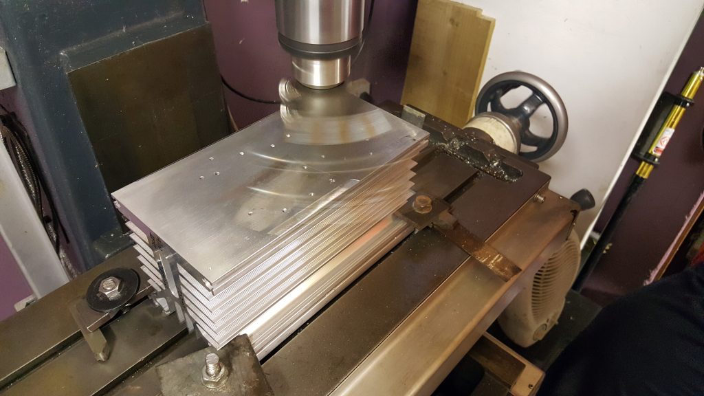
With the top and bottom of the head-spreader machined flat, a small end-mill cutter was used to machine the transistor slot to the correct depth following the skimming of the top surface. Then the heatsink mating surface was machined. Below you see the first cut on the heatsink.

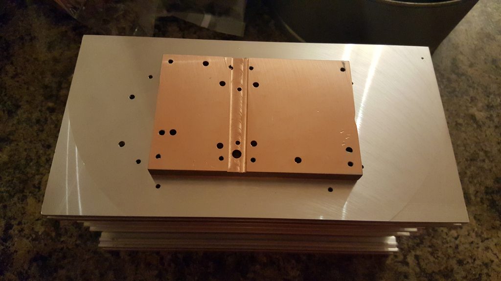
The finished parts. A few machining marks, but the surfaces are perfectly good enough. Some dents on the copper block, but it’s not worth removing all of the material to eliminate these.  Using a few drips of water as a substitute for thermal compound, the two mating surfaces stick together very well (with a good vacuum forming). That’s more than good enough for my needs!

Now I just need to wait for the parts to arrive before I can finalise the PCB and transistor mounting! This story continues here: Soldering Expensive Transistors.

Amateur Satellites & Dual-band Beams

Having attended a short talk by Steve M0SHQ at Essex Ham about operating Amateur Satellites, and seeing Steve work the ISS via APRS, I decided to have a go myself. I built the dual-band beam he recommended several times, but the design always measured up poorly. In the end I tweaked the design somewhat, and come up with something myself – it’s all credit to the original designer, I just optimised it with some antenna modelling software. Details on the antenna can be found here: Dual Band Satellite Yagi.

ircDDBGateway Basics

Over the past week or so, I have been playing around with DStarRepeater and ircDDBGateway to learn a bit about DSTAR repeaters, given the progress GB7KH‘s NoV is making. I have made a simplex hotspot with my FT817 and a soundcard interface, although I can see that there is certainly room for improvement. I have ordered a DVRPTR_V1 GMSK interface which has been dispatched so that will replace the soundcard, lowering the CPU load. I am to have the system set up on a Raspberry Pi 2 B, which was released yesterday (maybe today actually). I think I now understand how to tune up those Chinese notch filters, too.

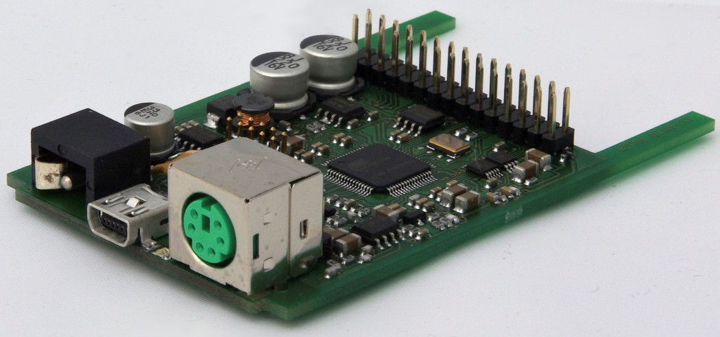
DVRPTR_V1 inside board