After building the 432MHz Yagi, I wanted a way of measuring the far-field pattern (radiation pattern) of the beam. At 432 megaHertz, the wavelength is pretty small and so creating a crude test range in the garden was possible – so I decided to do so. This page describes how I did it.

The far-field radiation pattern is regarded to start after 2 wavelengths from the RF source. Before that, the near-field pattern dominates, which has an unsettled radiation pattern. The pattern is usually said to have settled at a distance of $\tfrac{2D^2}{\lambda}$. This gives us the minimum distance between the source antenna (DUT) and our reference antenna (a dipole).
For our experiment, we need to observe the far-field pattern. To do this, we must be at least 2 wavelenths away from the RF source (or 432MHz Yagi).
So firstly, lets evaluate our two formulae:
We know:
- D – the main antenna dimention (this is the driven element length)
- D = 330.13mm = 0.33013m = 0.33m
- f – the frequency of operation, and therefore the wavelength, lambda
- f = 432.2 MHz
So we can calculate:
lambda = (3E8) / (432.2E6) = 0.694123091m = 0.70m (70cm)
2 x lambda = 2 x 0.694123091m = 1.39m
(2D^2)/(lambda) = (2(0.33013)^2)/(0.694123091) = 0.314024467m = 0.31m
At a distance of 0.31 metres, the fields should have settled and the far-field pattern become established. At a distance of 1.39 metres, we should be into the established far-field pattern. Using a distance greater than 1.39 is advisable, but is a minimum.
The Set Up
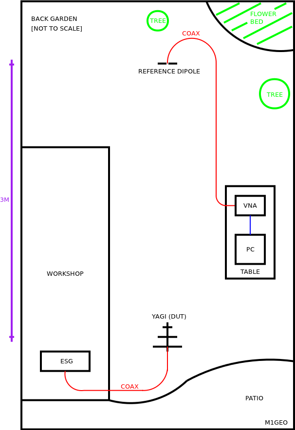
The diagram below shows the physical layout of the equipment used in this test.
- YAGI (DUT) is the Yagi that we are measuring (device under test).
- REFERENCE DIPOLE is omni-directional antenna used to receive the DUT’s transmissions.
- ESG is a RF signal source on the frequency of interest, here a HP ESA on 432.2 MHz @ 0dBm into the DUT.
- VNA is a calibrated RF signal receiver on the frequency of interest, here a DG8SAQv2 VNWA.
- PC is a HP 530 personal computer running the DG8SAQ v34.1b VNWA control software.
Making The Measurement
With the ESA and receiver (here, the VNA in spectrum analyser mode) set on the frequency of interest, set the ESA set to a suitable power level such that the receiver receives a strong signal when the beam directly faces the reference antenna. Using a protractor (see here for a printable one) it is possible to adjust the angle between the directional antenna under test (here, the 432MHz Yagi) and the reference dipole.
Factors such as the receiving dipole’s frequency response, gain, etc are not important, as they remain constant over all angles of the DUT, and so are eliminated when adjusting the ESA output power.
Starting with the reference dipole aligned on the testing Yagi’s bore-site, slowly rotate the testing Yagi about it’s axis. Tabulate the receive signal strength as a function of the test Yagi’s angle off bore-site. Depending on the symmetry of your antenna, you me be able to only do one half and then repeat it. Either way, you need to end up with signal strengths for angles in the range 0 to 360 degrees. Use as high resolution as you can. I did every 5 degrees but as you can see from the result, that it was not really enough. Some of the side-lobe details are lost.
Once you have a table of results, load them into your preferred number-crunching tool of choice; Microsoft Excel, LibreOffice, MathWorks MATLAB, gnuplot, etc. And plot them. For simplicity, I describe here the process for LibreOffice (as it is free software and available for most platforms [http://www.libreoffice.org/download/. This should be very similar for Microsoft Excel.
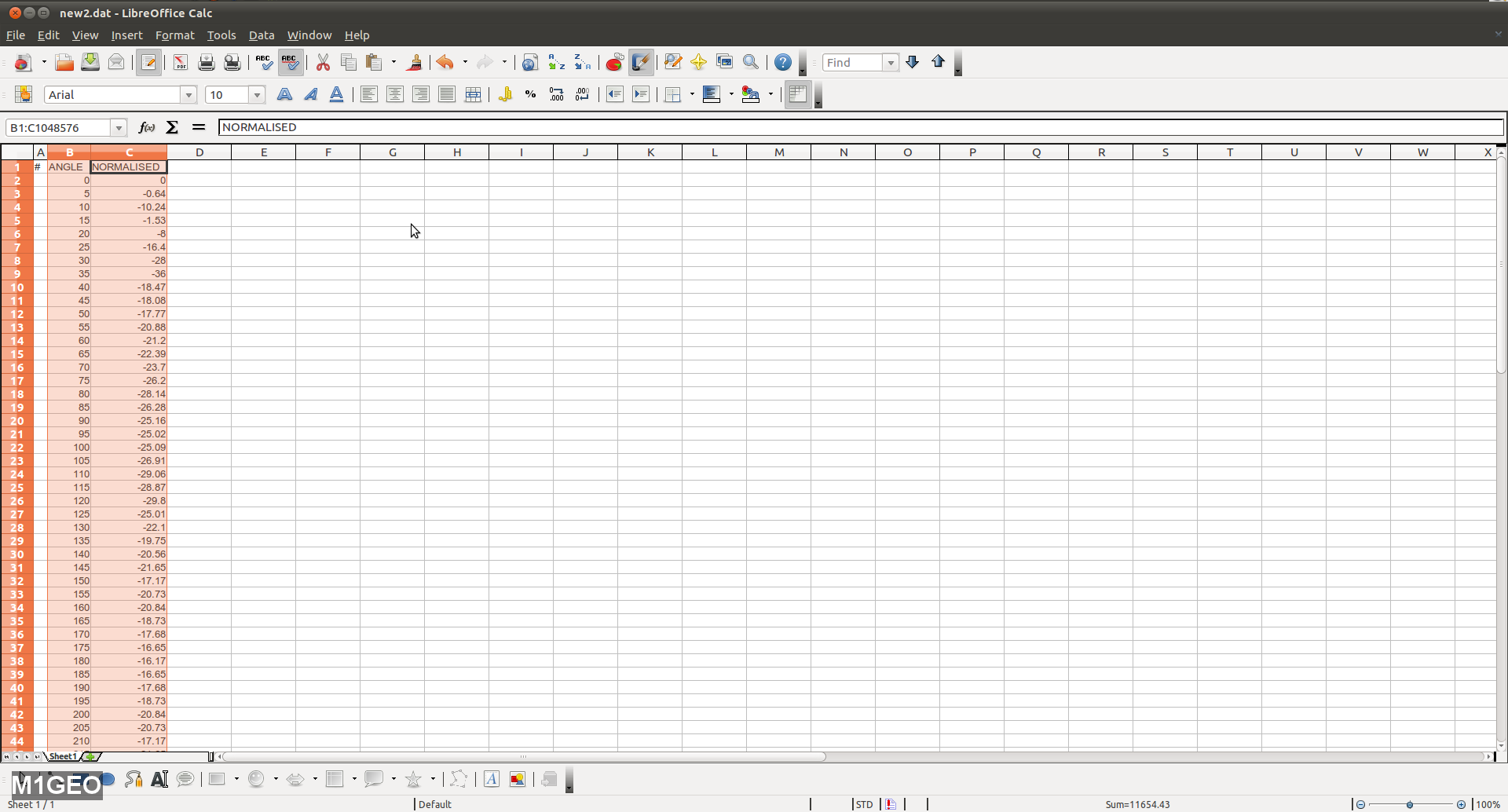
The first stage is to normalise the antenna’s gain (if you have not already done so) to 0dB. This can be done by adding an offset (in dB) to the value measured (equivalent of multiplying natural numbers to obtain a normalised value of 1). The largest value should be 0 dB, and will probably occur at bore-site (0 degrees). Once you have this, and it really is simple to do, you are ready to create a polar plot of you’re antenna.
The first step is to select the two columns you wish to plot. I have one column with the angle and another with the normalised gain measurement.
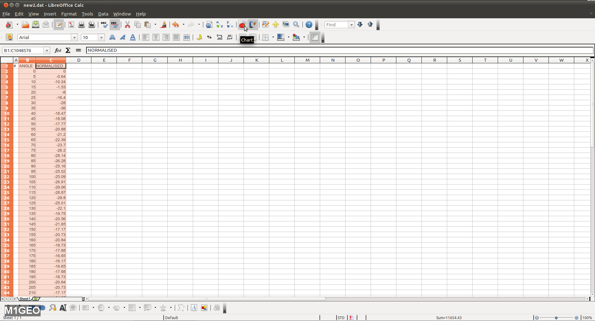
Next click the Chart icon (or Insert > Chart…) to open the chart wizard dialogue box.
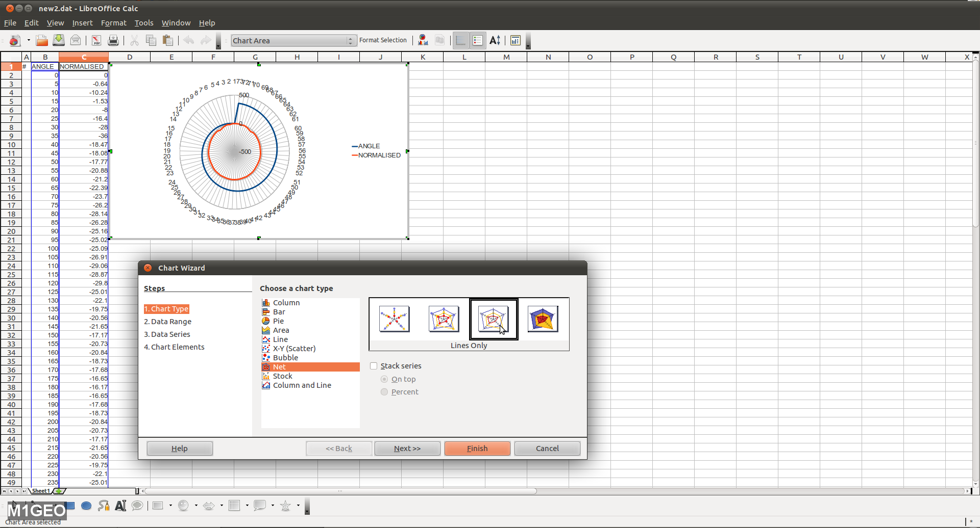
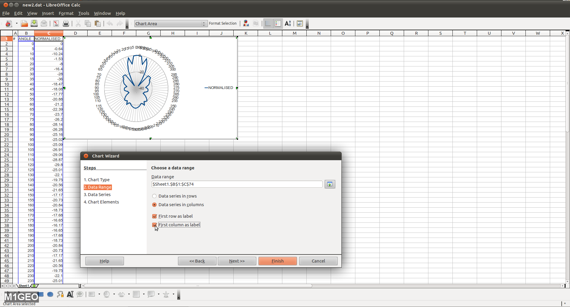
Once you’ve got the chart wizard, you need to select the Net (or Cobweb) type, and select to plot Lines Only (unless you want individual points – whatever suits you). Ignore the random mess of a chart you’re being shown.
In the next window, you tell the wizard that one of the columns has the labels for the other column. This is done with the First column as label tick option. You’re preview should look more sane now.
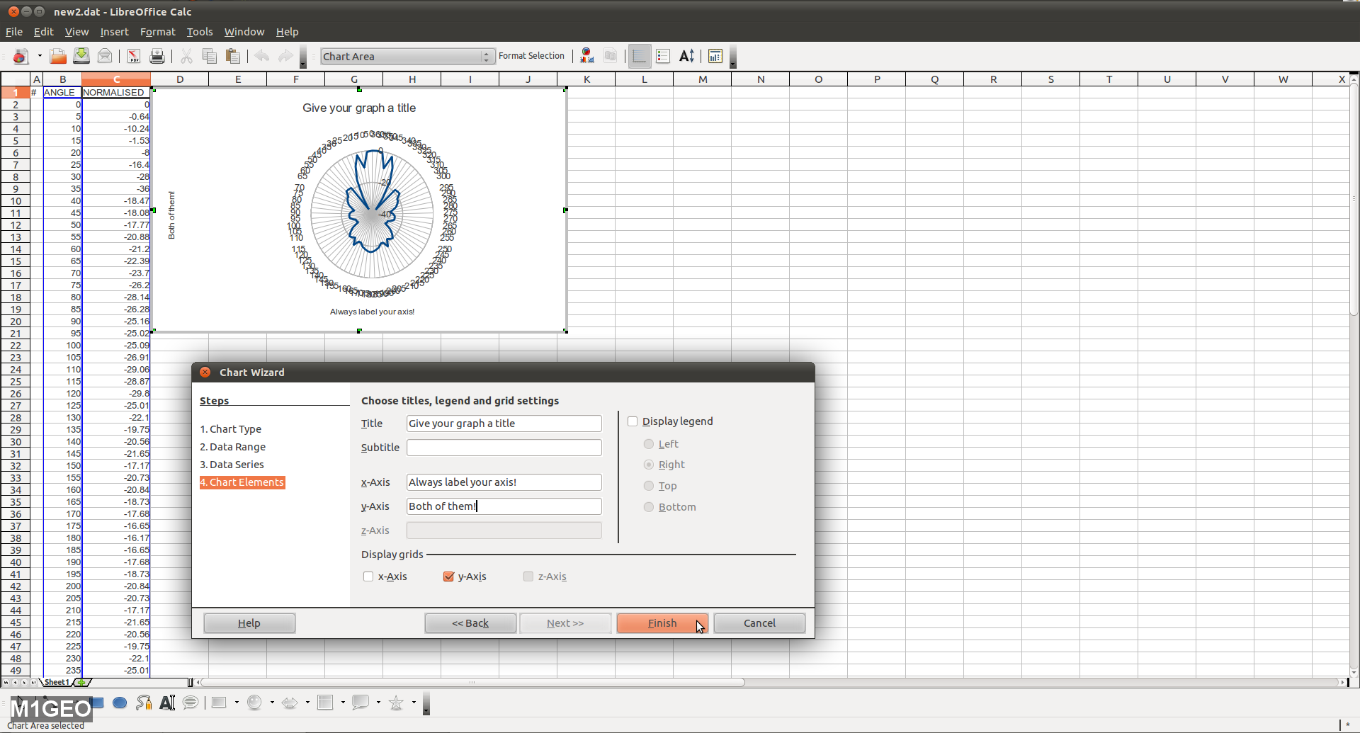
Finally label the graph up. All through my education, from secondary school to postgraduate level, it has always been hammered into me: label your graph, and label it well and always label each axis. This may not be appropriate for your graph, but I felt the need to stress it!
And there you have it. A polar plot in LibreOffice (maybe Excel too). Greater control is provided by gnuplot (free) and The MathWork’s MATLAB should you require it, but these are more complex.
The Result
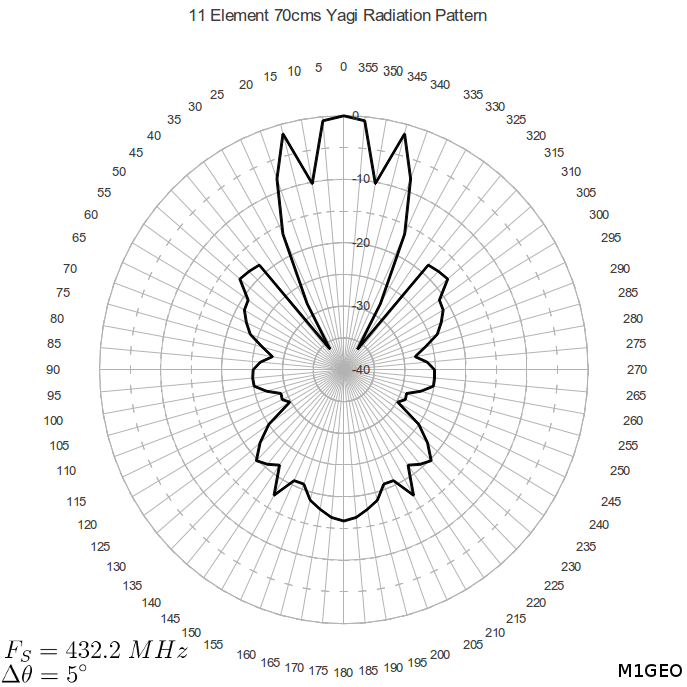
The image below is the result of testing above. As you can see it is under-sampled; resolution would need to be higher in order to fully view the nature of the lobes as they are masked by stronger lobes at this resolution. Antenna is the 432MHz Yagi.
VNWA
After getting the above result, I was keen to get a better method to assess the radiation pattern of the antenna. I used my DG8SAQ Vector Network Analyzer (VNWA) to try and achieve better results. In the RADAR mode, the VNWA transmits a signal on a specified frequency and then listens on the same frequency. Samples of received signal power are taken at specific moments in time, and as the antenna rotates slowly, produce the antenna radiation pattern we are all used to seeing. This section details a bit about how I did this with the VNWA. A good place to start is the help file for the VNWA, specifically the Antenna Radiation Pattern topic.
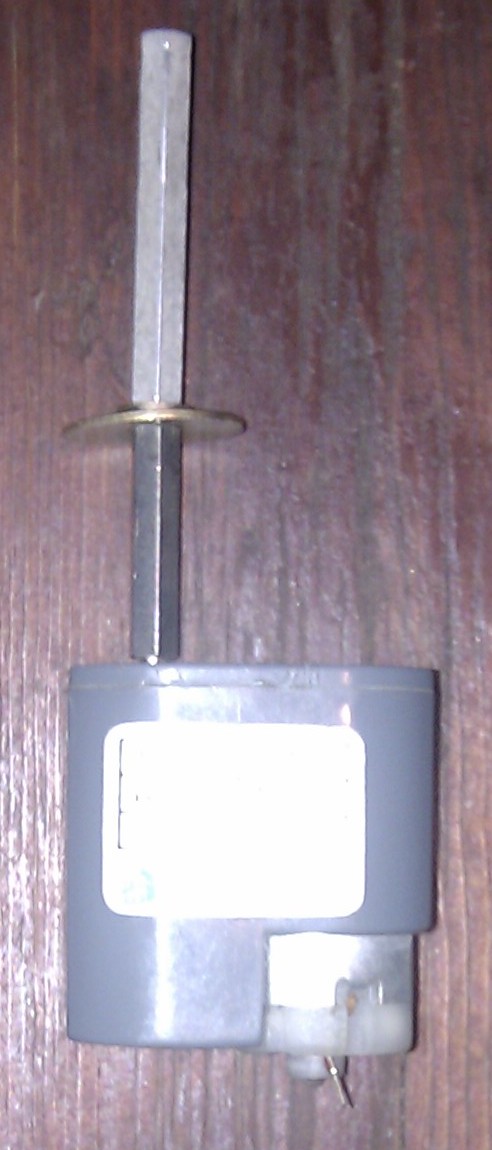
The setup was very similar to the setup described before; only this time a small electric motor was used to rotate the antenna. This motor was a 12V DC motor I bought with this idea in mind. It is geared down to 10 rpm. By dropping the input voltage to around 3V it was possible to get the rotation speed to around 3 rpm, or a rotation time of 20 seconds. This gives us enough samples to get a good representation of the antenna radiation pattern.
The next obvious question is how did I get an RF feed to the antenna. It initially seems a complex problem but after a little thinking, and some ideas from my father, we settled on using a short patch of coax to rotate with the antenna, and then using a series of coaxial connectors (which rotate freely, such as BNC) to connect to the static coaxial cable. This is not the perfect solution, but it worked well enough for me. I used a few connectors in series to ensure that it all rotated freely.
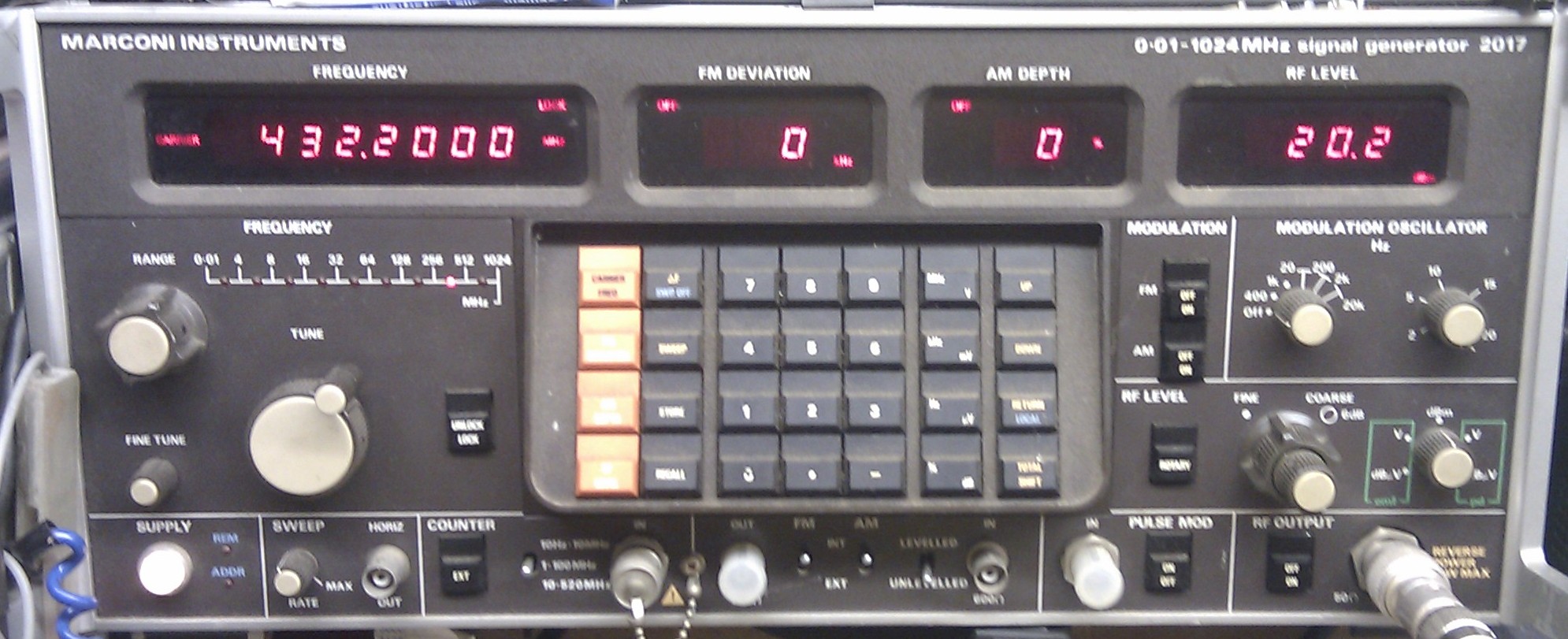
Initially the power output of the VNWA was too low (at -20dBm) and so it become clear from the outset that I would need to use the ESG as I had done in the previous experiments detailed above. Using a Marconi ESG with a power output of +20dBm made all the difference.
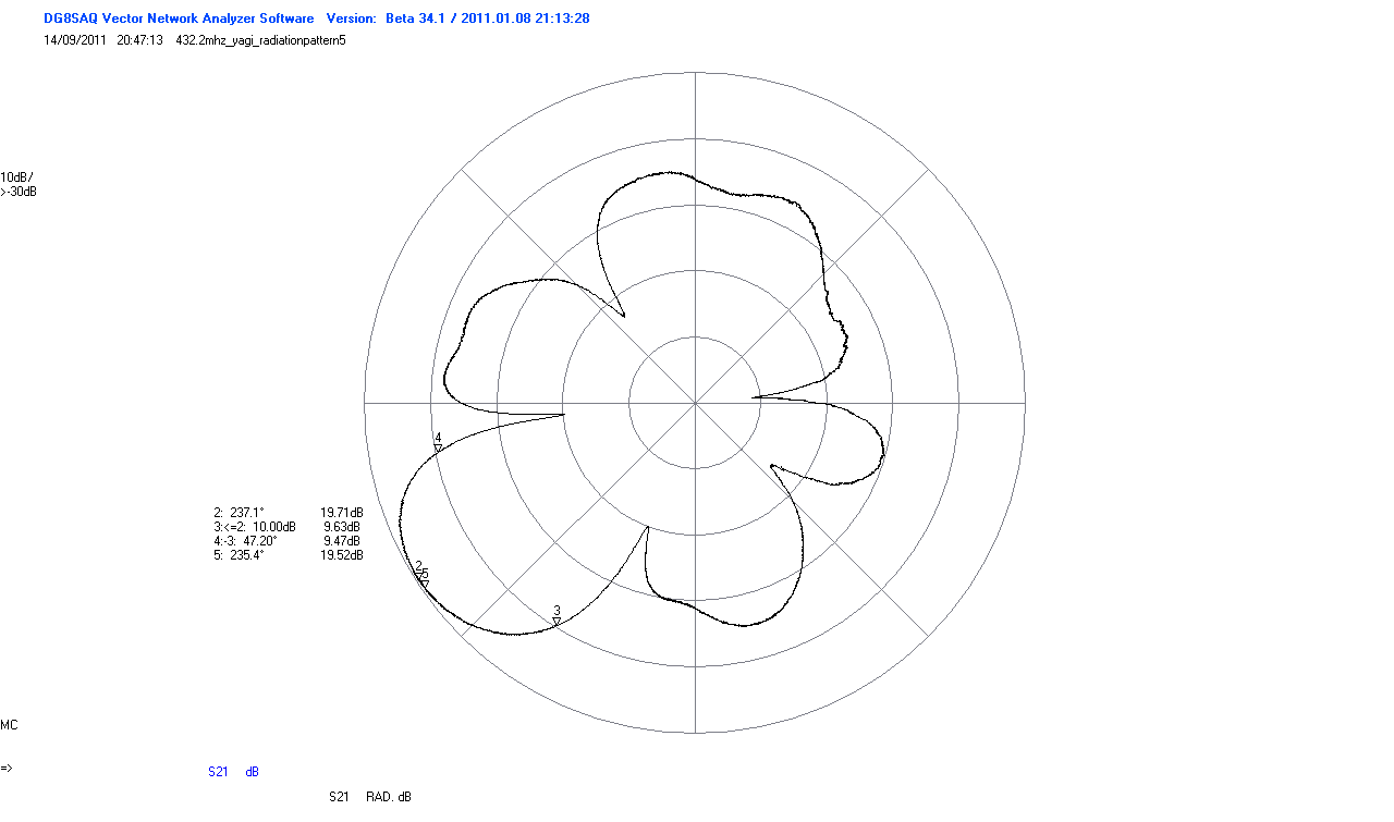
Using a simple dipole antenna as the receiving antenna I was the able to sample the received power and thus calculate the propagation pattern of the 432MHz Yagi at it rotates. The image below shows what the antenna’s radiation pattern looks like. There are still issues with it, but it is much better than the previous attempt.
Clearly here the main lobe is at 239 degrees. This is just an issue of triggering, and is nothing important. That is the front of the beam! However, you notice that the pattern is non-symmetrical. This is due to reflections from large surfaces (such as the workshop wall) and large metal garden furniture. If I get some time in the future, I will try and repeat this experiment in a large open area, such as a local park.

