When I was newly licenced, friend and fellow club Bill G0IQK member got me hooked on APRS. This has been a life-long interest of mine, mostly on 144.800 MHz with some diversions into LoRa APRS.
I remember Bill running APRS on the 30m band, and recently while chasing a few SOTA activations I heard the warbling of 300baud AX.25 on the top end of 10 MHz. I decided to dig into things a bit more, and this page is the outcome of my tinkering, about 20 years after I first knew of HF APRS.
How does it work?
Back in days gone buy, people used TNCs (terminal node controllers) to interface between the radio and the computer, The TNC was really a few things in the same box: a modem, for converting radio sounds into data; a controller, for interfacing with the computer; and a mailbox, for storing messages and forwarding them in the days before emails. However, nowadays we only really need the modem part.

What that means in reality is that we can take our standard HF radio set, connect it to our shack computer via USB (unless you own an Elecraft transceiver, in which case, you’ll need audio cables, a USB soundcard, etc.) and feed the receive audio into the computer.
We’ll use DireWolf (a software AX.25 packet radio modem. DireWolf is an excellent, open-source project: you can find everything you need (installers, documentation and get involved on their GitHub).
What does the modem do?
If you just want to decode things, skip this section.
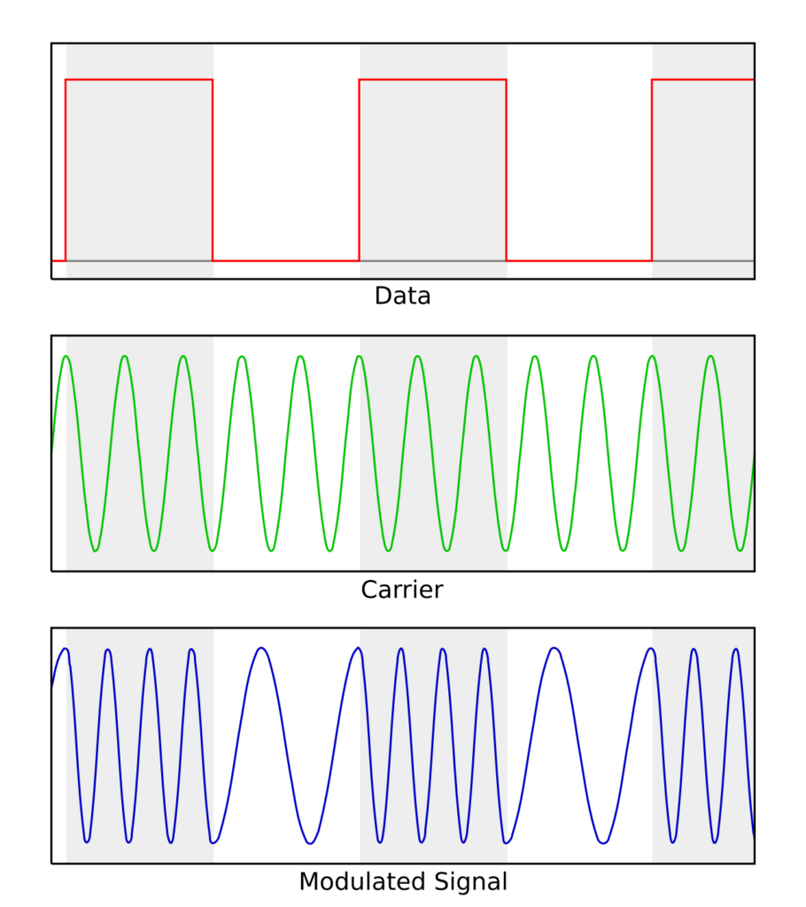
On the air, the APRS consists of 2-tones at audio frequencies (called the ‘mark’ and ‘space’). The transmitted audio shifts between these two frequencies to encode the binary data.

There are two things to note: (1) how frequently the tone shifts (i.e., how many times per second does the audio frequency change); and (2) difference in frequency between the two tones (i.e., how much the frequency shifts). The frequency with which the tone changes between mark and space is known as the baud rate of the data (point 1). The actual frequency difference between mark and space is specified by the protocol design; there are fancy ways of doing this efficiently, but that is out of scope for this (see MSK).
That these parameters (the baudrate and frequency shift) have a significant effect on the bandwidth of the transmitted signal and how tolerant it is of noise. On HF where bandwidth is more limited and the conditions more noisy, slower (lower baudrate) signals are desired.
| Baudrate (bps) | Mark / Space Frequency | Difference (Hz) | Notes |
| 300 | 1270 / 1070 | 200 | Mostly HF bands (Bell 103) |
| 1200 | 1200/ 2200 | 1000 | Mostly VHF (Bell 202) |
| 2400 | 2400 / 1200 | 1200 | Not common. QPSK (V.26 standard) |
| 4800 | 4800 / 2400 | 2400 | Not Common. 8PSK (V.27 standard) |
| 9600 | GMSK | 4800 | Mostly UHF (G3RUH) |
Since the audio frequency shift keying (AFSK) modems were originally designed to be used over telephone lines, the mark and space frequencies are expected to be quite accurate. This isn’t an issue when using AFSK on FM since any frequency offset is removed by the radio receiver, but on SSB the frequency offset can break things; both careful tuning and a reasonably calibrated radio (anything in the last 30 years?) should be fine.
The data is encoded in such a way that the change from mark to space (or space to mark) or the absence of a change represents the data, and so it does not matter if the tones are flipped; this means we can use either USB or LSB, as long as the tones appear on the correct frequencies.
Back when AX.25 was developed, forward error correction (FEC) which is now very prevalent was computationally expensive and so didn’t feature in the protocol. FX.25 adds a wrapper around an AX.25 packet (without requiring any changes to the AX.25 packet) to encapsulate it with FEC helping to improve the ‘ruggedness’ of the overall transmission to noise. DireWolf will understand and decode FX.25 packets as well as similar IL2P packets. The magic part is, since the original AX.25 packet remained untouched, so will any legacy hardware, since it’ll just ignore the FEC wrappers as noise and decide the original AX.25 payload if it can. It’s worth using FX.25 if you are planning on transmitting, since several software modems support it. See the instructions in the DireWolf FX25 manual.
Where should I listen?
The next step in our puzzle is that DireWolf does not use the Bell 103 frequencies for 300 baud AX25. Instead, it choses a 1600 Hz space tone and an 1800 Hz mark tone. We can confirm this by starting DireWolf with the MODEM 300 directive:
Channel 0: 300 baud, AFSK 1600 & 1800 Hz, A+, 44100 sample rate / 3The table below summarises some of the common HF APRS frequencies, calculated for DireWolf 1600/1800 Hz tones:
| Band | Baudrate | Dial Frequency (MHz) | Notes |
| 80 metres | 300 | ||
| 40 metres | 300 | 7.0452 USB 7.0486 LSB 7.0472 LSB 7.1040 LSB | |
| 30 metres | 300 | 10.1476 USB | This is what I am using here. |
| 20 metres | 300 | 14.1023 USB 14.1030 LSB 14.1050 LSB | Legacy Net105 |
| 10 metres | 300 | 28.1400 LSB | |
| 10 metres | 1200 | 29.2500 FM 28.1371 USB |
Knowing exactly where to listen seems to be quite tricky, but once you recognise the 300 baud Bell 103 tones, you’ll have no trouble fine tuning. All I can say is that I have successfully heard APRS on 40m and 30m. The rest of this page uses 10.1476 MHz USB (30 metres).
Decoding packets
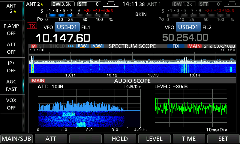
Depending on conditions, you’ll hear 300 baud packets on one of the frequencies above. You can see in the audio scope section of the radio screen that there are two different signals both on entirely different and non-overlapping frequencies. This is where a software modem such as DireWolf really shines!

DireWolf (and many other software modems) can be configured to run multiple decoders within the audio bandwidth, maximising the likelihood of a positive decode. With DireWolf, this can be achieved by specifying the number and spacing of the decoders on the modem configuration line. For example, 9 separate modems at 30 Hz spacing would be configured like:
MODEM 300 9@30Another useful trick up the sleeve of the software modem is the ability to “correct” bit errors: in practice, what this means is that if the modem receives a packet with a failed checksum (i.e., some packet corruption was encountered), the tool will flip each and every bit in the received packet, and check if the packet then passes the checksum. This is useful for handling simple errors. DireWolf also supports flipping multiple bits, but this increases the chance that we allow a non-sense packet through by brute force. This is done by adding a slash and the number of bits to try correcting, so for example the recommended 1-bit correction can be configured as such:
FIX_BITS 1Finally, it’s also possible to change the modem type/algorithm, by adding its letter in the command. I found E worked well, although it is a little compute intensive.
MODEM 300 9@30 E /2Once the DireWolf modem is running, you’ll see decodes in the terminal window. There is a lot of information in the window. Green colour text is from the DireWolf program, and is telling you about the signal & payload. You can see the audio level, the number of bits corrected (NONE or SINGLE) and the tuning within the audio passband (i.e., which of the multi-decoders received the packet). The blue colour text is the received data itself, which is passed on to an application to use. That’s pretty much it for receiving packets with DireWolf.

For mapping the packets, many options exist:
The classic tool for Windows, UI-View by G4IDE (sk) is old, but still functional. It’s well supported and was commonly used back in Windows 95 days. Xastir is another firm favourite for Linux/Unix users, which is very feature rich. More modern clients for Windows include PinPoint, APRSISCE/32, and YAAC.
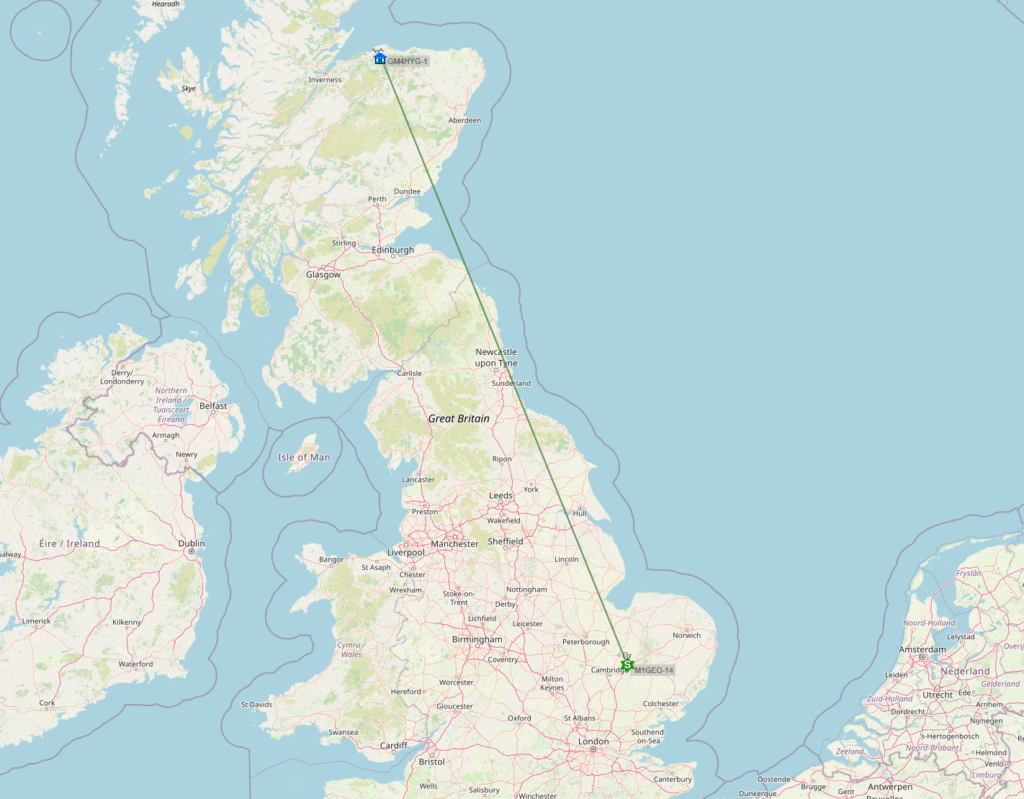
A final option, and probably something to do regardless, is to push any decoded packets to the APRS-IS network thus turning your receiver into an internet gateway or iGate. This means that decoded packets will show up on online viewers like APRS.fi and similar. Below, I have configured my IC-7610 to upload as M1GEO-14 for a few hours, and the online tools make it very easy to see who you can hear:

Transmitting
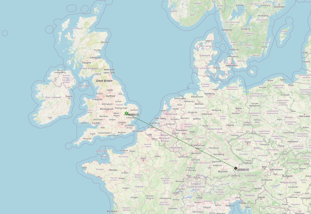
I wasn’t intending to transmit, but there was nothing stopping me. So I decided to give it a go. Transmitting is really out of the scope of this blogpost, but, the main points are that you need to add a beacon PBEACON directive and a means to PTT (I just used RTS on the Icom IC7610, as its easy) with PTT COM4 DTR. You can see that my very first transmission was received by OE5DXL-10 in Upper Austria on the Austria-Germany border.


It is important not to make a menace of yourself on HF APRS, so beacons should be infrequent (~30 minutes seems to be the standard), and if you decide to digipeat, use short paths and long wait delays to allow others to digipeat first.
Transmitted text, such as the below digipeat transmission, appears in magenta:

Then, it’s just a matter of time to let things happen!
APRS.fi will show you a monthly list of people who received your beacons (these are my first two transmissions):

Best distance here goes to VE2GQF-2 at 3175 miles. Nice.
My Final Configuration
So, my final configuration for the iGate & Digi on 30M is as follows:
# M1GEO APRS 300BD IGATE
# https://www.george-smart.co.uk/

# Set up radio link
ADEVICE 0 11
CHANNEL 0
FX25TX 1
FIX_BITS 1
MODEM 300 9@30 E /2
PTT COM4 DTR

# Specify My Call (make sure this matches your IGLOGIN call)
MYCALL M1GEO-14

# Allow digipeating on RF
DIGIPEAT 0 0 ^WIDE[3-7]-[1-7]$|^TEST$ ^WIDE[12]-[12]$ TRACE

# Send Beacons
# RF
PBEACON delay=1 every=30 overlay=S symbol="digi" lat=00^00.00N long=0^00.00E power=10 height=40 gain=3 comment="M1GEO 30M APRS" via=WIDE1-1,WIDE2-1
# INET
PBEACON sendto=IG delay=1 every=60 symbol="igate" overlay=T lat=00^00.00N long=0^00.00E power=10 height=40 gain=3 comment="M1GEO 30M APRS"

# Log in to APRS-IS
IGSERVER london.aprs2.net
IGLOGIN M1GEO-14 13974

# Allow NET to RF for those heard on RF
IGTXVIA 0 WIDE1-1
Note that in the above text, my latitude and longitude have been retracted. You can find yours easily online using Google Maps or APRS.fi. I chose to allow INET to RF traffic for stations heard. This is useful for remote stations (like SOTA ops) to send/receive messages when they have no cellular coverage, for example for self spotting and messaging loved ones to say they’re still alive while out walking (my main use for it).
Closing remarks
Firstly you should be aware of what is and is not legal in your area with regard to transmitted bandwidths, automatic operation, bands, etc.
Secondly, you should consider the radio you are using to transmit, should you chose to do so. Something that is spectrally clean as well able to click in-to/out-of transmit many times. Antennas should be out of the way of people touching them, and robust as you won’t always be looking at the radio’s SWR meter should the antenna fail.
Finally, read the manual for DireWolf; it’s well written and contains lots of excellent information on how to use the tool and how to get the best performance – we all want the best performance, after all…
