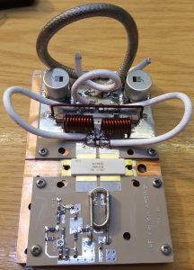
Those of you who have been following this project evolve will have seen how I soldered the transistor to the heat-spreader and before that how I machined the heat-spreader & heat-sink after their initial use. Most recently, I have been building the new W6PQL pallet, based on the revision 4d schematic, found here.
This pallet offered several design changes compared to the original F1JRD design. The first is temperature tracked biasing for the FET. The F1JRD pallet didn’t have temperature tracking, but the W6PQL design uses a combination of 10kOhm and 22 kOhm NTC thermistors to track the temperature change of the pallet. A 6V Zener diode is used to clamp the bias supply and to also limit the maximum gate voltage the FET can see. A small 200 Ohm pot allows the bias to be adjusted to get the correct quiescent current. This is the next task.
The story continues with the initial power-up testing! First I need to commission my new General-Electric 50V/40A PSU I brought at the Rosmalen Hamfest back in early March.

